Your cart is currently empty!


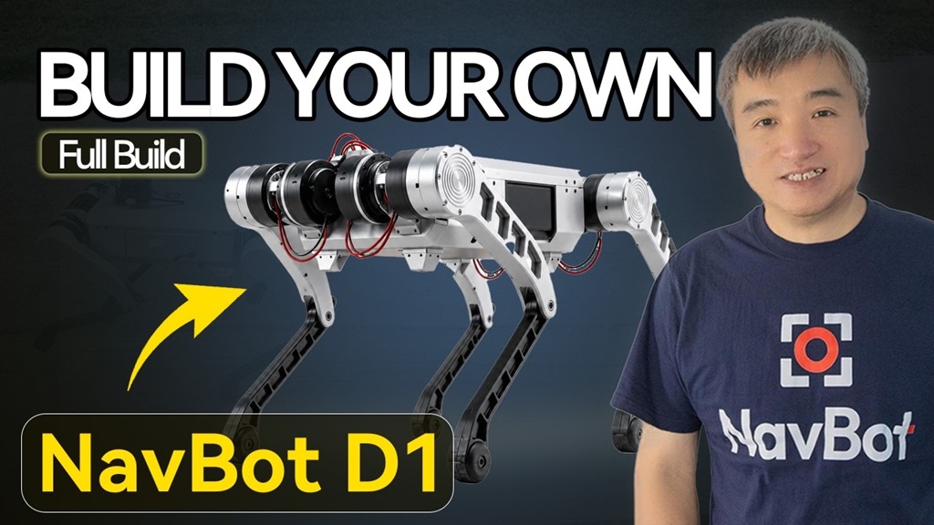
NavBot-D1 is an open quadruped robotics platform for developers. Its value is not just that it can walk, but that it connects mechanical design, actuators, onboard computing, ROS 2, CAN bus, remote control, and reinforcement-learning locomotion into a system that can be reproduced, modified, and extended.
NavBot-D1 is positioned as an open development platform rather than a closed consumer robot dog. It is designed for industrial-grade development, inspection, safety, field operation, and robotics research. The product page lists several key specifications:
- Up to 97 N-m peak joint torque
- 25 kg payload capacity
- All-metal aluminum alloy frame
- Reinforcement learning-based locomotion
- Jetson Orin Nano Super 8G onboard computing
- 2-hour battery life
- GPS, LoRa, and real-time image transmission capability
This article follows the build as an engineering reproduction guide. We will start from the system goal, then walk through the hardware list and architecture, and finally connect mechanical assembly, Jetson bring-up, ROS 2, IMU/CAN validation, actuator IDs, calibration, and reinforcement-learning gait testing into one reproducible path.
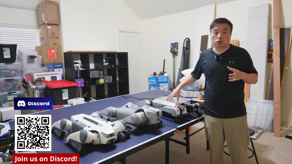
Project Overview
NavBot-D1 can be understood as a complete 12-DOF quadruped robot development kit. Its basic control loop looks like this:
Remote input / LoRa
      ↓
Jetson Orin Nano Super 8G
      ↓
ROS 2 drivers, state estimation, RL locomotion policy
      ↓
USB-CAN / CAN bus
      ↓
12 joint actuators
      ↓
IMU feedback + physical locomotion
If you have built ROS 2 rovers, robotic arms, or desktop robots before, the main difference with NavBot-D1 is that this is not a slow wheeled chassis. It is a dynamic legged system. A wheeled robot can usually stop in place when control goes wrong. A quadruped with incorrect joint direction, ID mapping, zero position, or policy output can fall immediately. For NavBot-D1, the engineering sequence matters more than any single command.
I recommend splitting the reproduction process into four layers:
| Stage | Goal | Success Criteria |
|---|---|---|
| Hardware bring-up | Mechanical structure, power, main board, Jetson, IMU, and CAN all work | Stable power-on, working emergency stop, SSH access |
| Actuator bring-up | 12 actuator IDs, directions, and zero positions are correct | Each leg moves consistently with the body coordinate frame |
| Standing test | The robot can stand and switch modes reliably | Repeated power cycles lead to repeatable standing behavior |
| Locomotion test | The RL policy drives controlled quadruped motion | Forward, backward, turning, and speed commands match remote input |
This is also how the rest of this article is structured. We will not treat NavBot-D1 as a pile of parts. We will treat it as a layered robot system that must be validated step by step.
Core Hardware List
The diagram below reorganizes the BOM by function. This is also how I recommend managing the parts during a real reproduction, because each layer has a different failure mode.
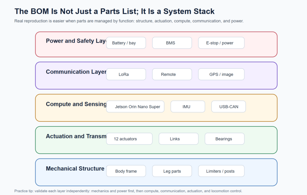
| Module | Main Parts | Role | Reproduction Focus |
|---|---|---|---|
| Mechanical load-bearing layer | Body frame, upper/lower legs, support posts, limiters, battery bay | Carries the body, battery, actuators, and impact loads | Hole alignment, orientation, stiffness, limit range |
| Actuation and transmission layer | 12 actuators, knee connectors, bearings, linkages | Provides 12 leg joints | ID, direction, zero position, linkage interference |
| Onboard compute layer | Jetson Orin Nano Super 8G, main board, cooling | Runs ROS 2, drivers, and RL policy | Flashing, networking, SSH, thermals |
| Sensing and bus layer | IMU, USB-CAN, CAN wiring | Provides attitude feedback and actuator communication | Device enumeration, permissions, data rate |
| Communication layer | Remote controller, LoRa, GPS, image transmission module | Supports indoor/outdoor control and longer-range operation | Frequency, distance, open-area testing, antenna mounting |
| Power and safety layer | Battery, BMS, power button, emergency stop, power distribution | Powers Jetson, peripherals, and actuators | Battery state, emergency stop, wire gauge, connector retention |
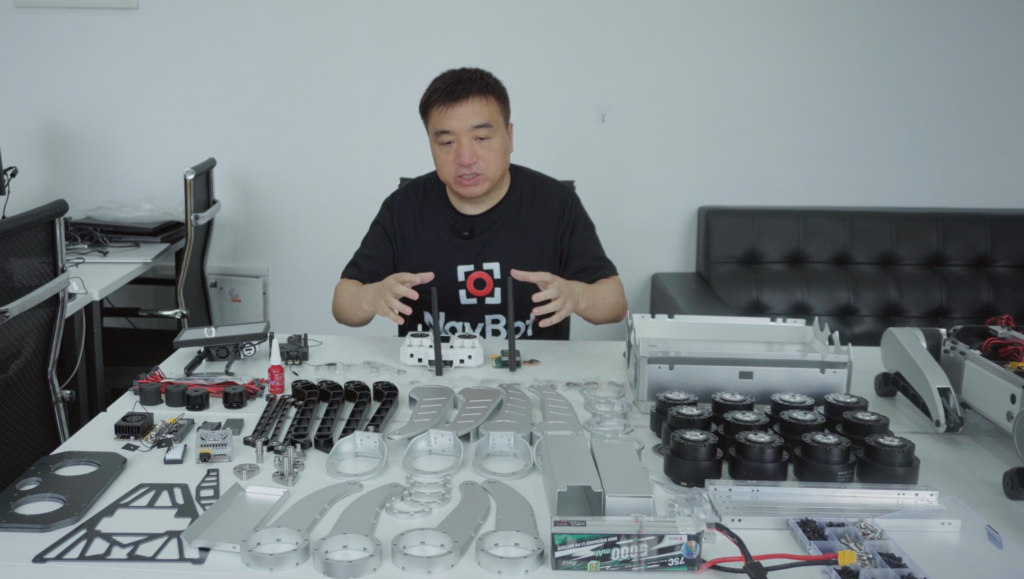
One common mistake is to treat the BOM as a purchase list only. For a quadruped robot, every component should be tied to a validation action. For example, validating the IMU does not mean it is physically plugged in. It means you can read reasonable roll, pitch, yaw, or raw IMU data from the software stack. Validating CAN does not mean the USB-CAN adapter lights up. It means the adapter is detected, the bitrate is configured, and messages can be exchanged with the actuators.
System Architecture
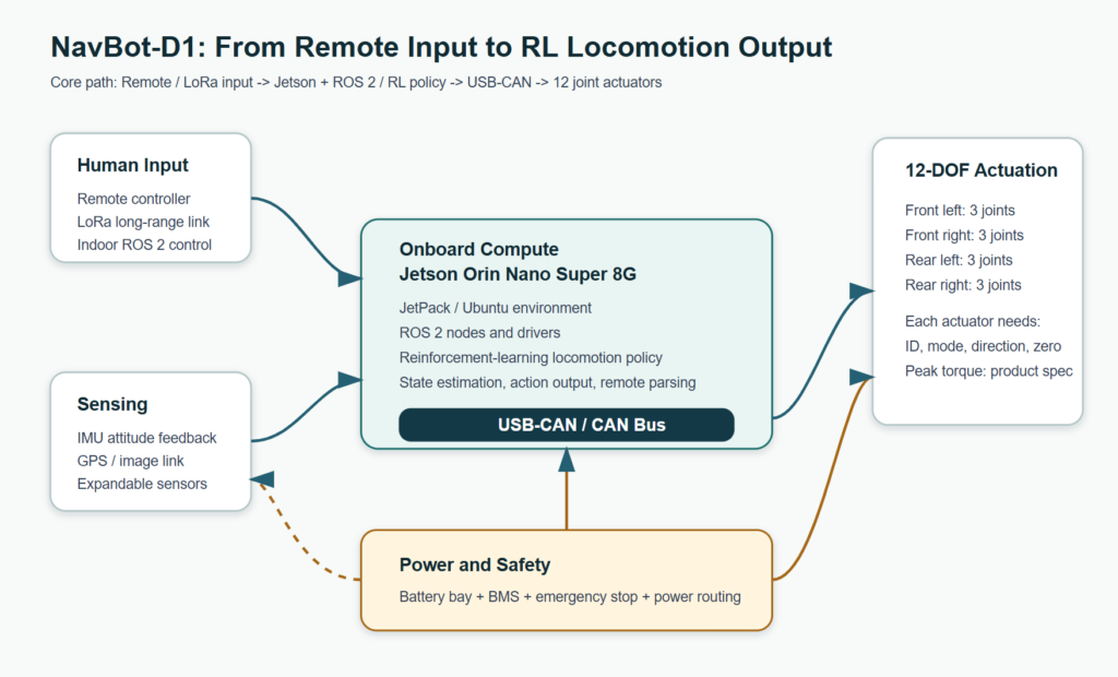
The NavBot-D1 system can be divided into three main paths:
- Control path Remote input or LoRa commands enter the Jetson. ROS 2 nodes parse the command, then the RL policy or locomotion controller produces joint targets.
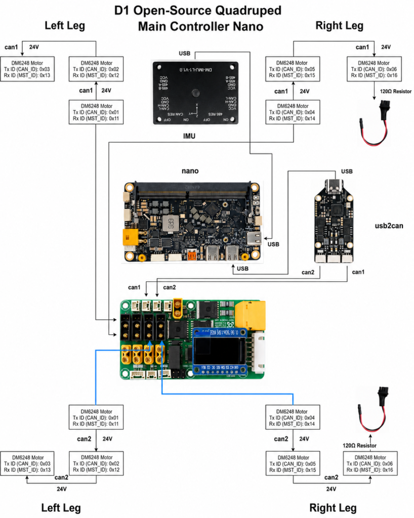
- Actuation path Jetson communicates through USB-CAN to the CAN bus, then sends joint targets to the 12 actuators. The actuator ID, direction, and control mode determine whether software commands map correctly to physical joints.
- Feedback path The IMU provides body attitude feedback, and the actuators also report state. For a quadruped, attitude, joint position, motor status, and control mode must be managed by the same system state machine.
A few terms should be normalized before we continue:
| Ambiguous Expression | Engineering Meaning |
|---|---|
| accurator | actuator / joint actuator |
| canvas | CAN bus |
| Nora | LoRa module |
| resource learning | reinforcement learning |
| Jet Nano / Jettison | Jetson Orin Nano Super 8G |
All later steps follow these three paths: make the hardware mechanically reliable, make Jetson maintainable, bring up ROS 2 and CAN, then move to standing and gait testing.
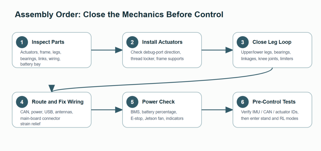
Step 1: Prepare the Mechanical Parts
The mechanical build should begin with parts inspection, not immediate assembly. Once a quadruped is half assembled, discovering that a bearing, spacer, screw, or linkage is oriented incorrectly can cost a lot of time.
I recommend laying out and checking parts in this order:
- Body frame, side plates, top plate, and bottom plate.
- Upper legs, lower legs, and knee joint connectors for all four legs.
- Bearings, linkages, limiters, and support posts.
- All 12 actuators, with temporary labels for their future leg and joint positions.
- Battery bay, BMS, main board, Jetson, IMU, USB-CAN, and wiring.
- LoRa, remote controller, GPS, image transmission module, and antennas.
Here is a practical rule: do not wait until actuator ID writing to decide where each actuator belongs. Before mechanical assembly, label each actuator temporarily, such as FL-HIP, FL-THIGH, and FL-CALF. This makes later ID writing, CAN wiring, and zero calibration much less error-prone.
Step 2: Assemble the Actuators and Main Frame
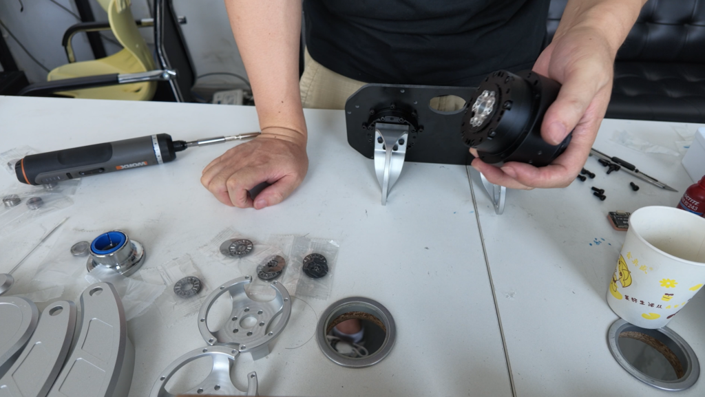
The first parts to secure are the actuators and the main frame. Three details are especially important:
- Keep debug ports accessible: actuators may need ID rewriting, parameter reads, or debugging later. If the frame blocks the debug port, maintenance becomes painful.
- Use a small amount of thread locker on critical screws: legged robots vibrate heavily, especially around actuators, linkages, and support structures.
- Manually move each layer after assembly: do not wait until all four legs are complete to discover that one joint is binding.
You can assemble one side first and then mirror the process on the other side. Each leg should be checked for:
- Hip actuator mounting strength.
- Alignment between the upper leg and actuator output.
- Proper bearing insertion at the knee joint.
- Smooth linkage motion.
- Limiters that prevent unsafe over-rotation.
For a quadruped, mechanical limiters are not decorative parts. They prevent joints from rotating into dangerous positions during software faults, manual handling, or falls. Mechanical limits and software limits should both exist. Do not rely on the control policy alone.
Step 3: Wire the Power, Main Board, Jetson, IMU, and CAN
After the mechanical loop is closed, the next step is wiring. A useful rule is: power first, signals second; secure first, debug later.
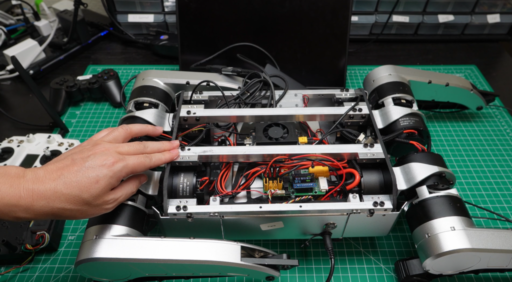
A typical connection structure looks like this:
Battery
├── BMS / power management
├── Emergency stop / power switch
├── Main board power input
├── Jetson power
├── External module power
└── Actuator power path
Jetson
├── USB → IMU
├── USB → USB-CAN adapter
├── USB → LoRa / receiver module
├── HDMI / keyboard / mouse for first boot
└── Ethernet / Wi-Fi for SSH
Cable routing is one of the easiest areas to underestimate. NavBot-D1 runs, turns, and absorbs impact from the ground. Every cable should satisfy three requirements:
- It must not be pulled when joints move.
- It must not be crushed by actuator housings during a fall or when the robot is carried.
- Its purpose must remain visible for later maintenance.
Power should be validated separately. For the first power-on, do not enable the actuators immediately. Confirm:
- BMS display and battery state are normal.
- The emergency stop can reliably remove dangerous output.
- The Jetson fan starts.
- Main board indicators look normal.
- Peripheral power rails are stable.
Step 4: Flash Jetson and Create a Maintainable Base System
The first software task is to turn Jetson into a maintainable compute node. Do not rush into robot code.
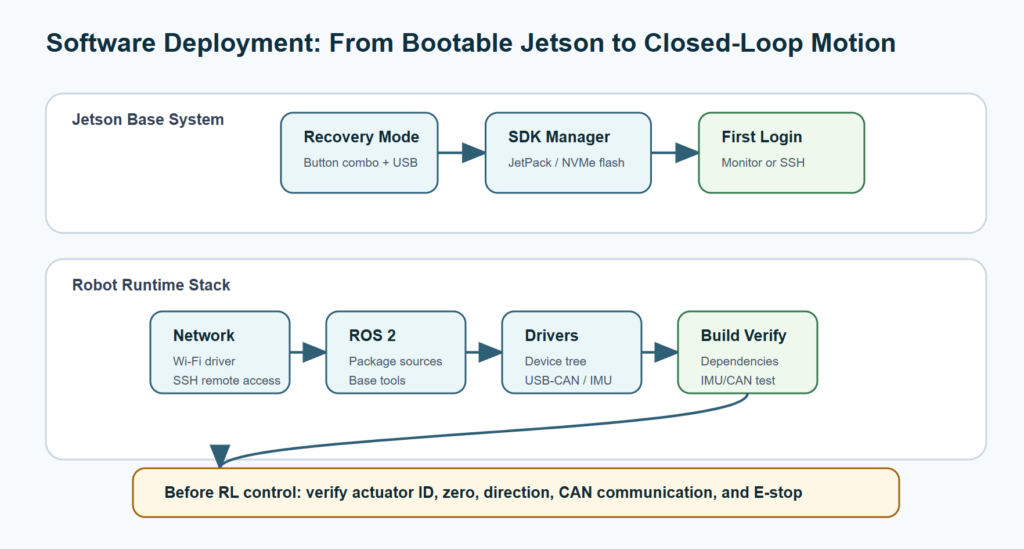
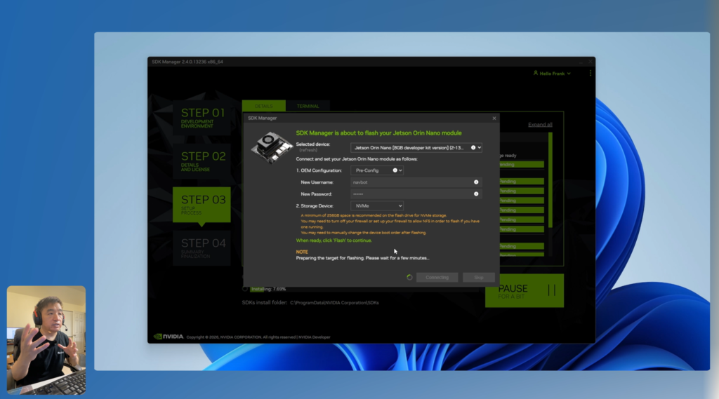
Recommended flow:
- Put Jetson into recovery mode.
- Use NVIDIA SDK Manager to flash JetPack.
- Select NVMe as the target disk so the system has enough space.
- Connect monitor, keyboard, and mouse for the first boot.
- Create the user account and verify the desktop and base network.
- Get the IP address and switch to SSH.
Why switch to SSH early? Later steps involve ROS 2 setup, dependency installation, driver builds, and log inspection. SSH makes command reuse and log capture much easier than working directly from an attached monitor.
The acceptance criteria for this stage are simple:
Host computer → SSH → Jetson
Jetson → Internet / local network
Jetson → can reboot and reconnect
Only after these are stable should you move to ROS 2 and driver installation.
Step 5: Install ROS 2, Wi-Fi Driver, Device Tree, and Dependencies
Once the base Jetson system is ready, the next layer is the robotics runtime stack. This usually includes:
- Configuring ROS 2 package sources.
- Installing ROS 2 base packages and build tools.
- Installing the Wi-Fi driver so the robot is not tied to Ethernet.
- Configuring the device tree so hardware interfaces are exposed correctly.
- Cloning the main NavBot-D1 project.
- Installing dependencies and building the workspace.
It is better not to hard-code a one-time command sequence here, because JetPack, ROS 2, kernel versions, and project scripts may change. A more reliable approach is to preserve the flow and validation points:
| Subsystem | Goal | Validation |
|---|---|---|
| Wi-Fi | Jetson joins the local network wirelessly | SSH still works after unplugging Ethernet |
| ROS 2 | Base environment is usable | Environment can be sourced and base tests run |
| Device tree | Hardware interfaces are recognized | Device nodes remain stable after reboot |
| Dependencies | Project can be built | Workspace build completes without key errors |
| IMU | Attitude data can be read | Roll/pitch/yaw or raw IMU data changes reasonably |
| USB-CAN | CAN adapter is usable | Device enumeration, bitrate setup, and send/receive tests pass |
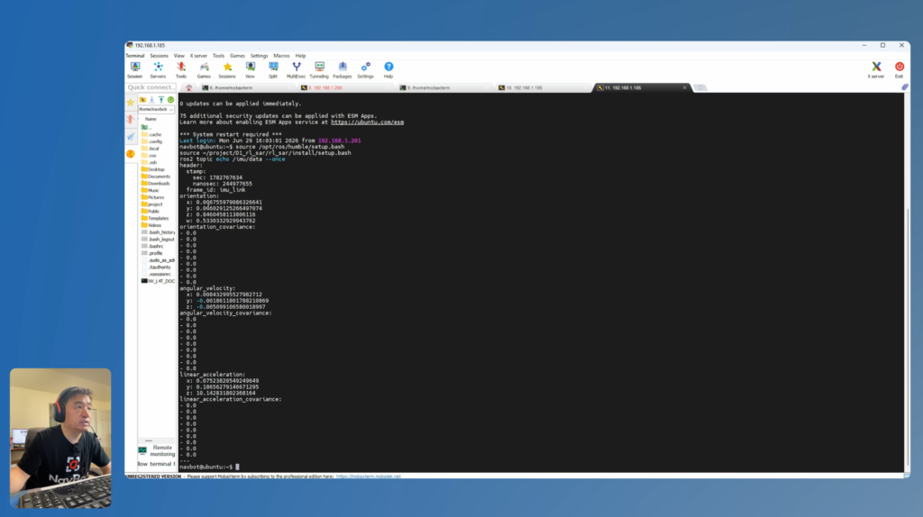
Logs matter during quadruped bring-up. Save the output of every build, driver installation, and device test, especially logs related to the CAN adapter, IMU, and actuators. If gait fails later, the policy is not always the problem. The lower-level interface may be unstable.
Step 6: Configure the CAN Bus and Actuator IDs
CAN bus is the execution path of NavBot-D1. Jetson produces joint targets, but the 12 actuators on the CAN bus are what actually move the legs.
Before entering reinforcement-learning control, each actuator must be handled individually:
- Connect one actuator at a time.
- Write or confirm the actuator ID.
- Set the control mode and required parameters.
- Reload the parameters and read them back.
- Record the leg and joint that this actuator belongs to.
- Move to the next actuator.
Do not connect all 12 actuators and then guess which one is which. For a quadruped, an ID mistake is direct: software may think it is controlling the front-left hip while the rear-right knee is moving.
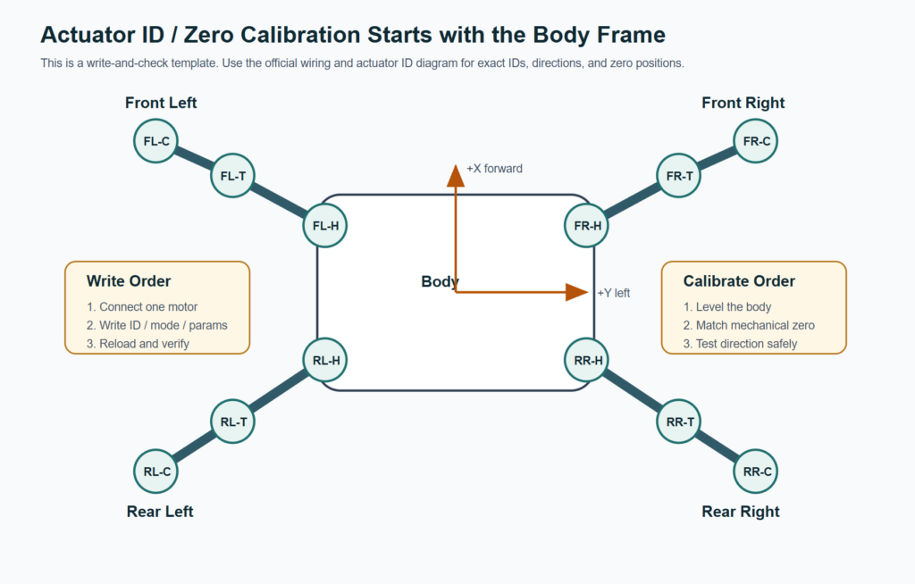
Create an actuator mapping table:
| Leg | Joint | Temporary Label | Final ID | Direction | Zero Position |
|---|---|---|---|---|---|
| Front Left | Hip | FL-HIP | Follow official docs | To verify | To calibrate |
| Front Left | Thigh | FL-THIGH | Follow official docs | To verify | To calibrate |
| Front Left | Calf | FL-CALF | Follow official docs | To verify | To calibrate |
| Front Right | Hip | FR-HIP | Follow official docs | To verify | To calibrate |
| Rear Left | Hip | RL-HIP | Follow official docs | To verify | To calibrate |
| Rear Right | Hip | RR-HIP | Follow official docs | To verify | To calibrate |
This table is not paperwork. It binds mechanical placement, wiring, software coordinate frames, and debugging records together. If one leg moves in the wrong direction later, this table helps isolate whether the issue is ID mapping, motor direction, zero position, or control output.
Step 7: Calibrate Zero Position and Validate Joint Direction
Calibration is a hard gate before real locomotion. A 12-DOF quadruped cannot rely on a rough “looks close enough” mechanical pose.
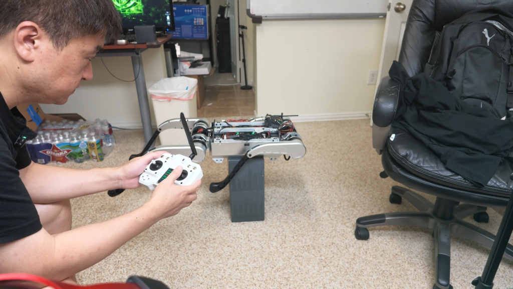
Recommended calibration order:
- Place the body level An uneven table or floor will contaminate the zero position. Use a level or fixture if possible.
- Make all four leg poses consistent Front/rear and left/right leg poses should be comparable. Do not calibrate with one leg bent and another extended.
- Test each joint with small commands Move one joint at a time and confirm direction against the body coordinate frame.
- Use low torque or a safe mode first Do not start the first test in a high-output state.
- Confirm emergency stop behavior Before proving that the robot can stand, prove that it can stop safely.
Before standing, answer these questions:
- Is every actuator ID unique?
- Do software labels for front-left, front-right, rear-left, and rear-right match the physical robot?
- Does each joint’s positive direction match the control definition?
- Does the IMU attitude match the body orientation?
- Can the emergency stop intervene immediately if actuator output becomes unsafe?
If these questions are not answered, entering RL mode is not responsible engineering.
Step 8: Enter Reinforcement Learning Locomotion Mode
After mechanical assembly, power, Jetson, ROS 2, IMU, CAN, and actuator mapping all pass validation, the robot can enter reinforcement-learning locomotion testing.
Recommended first run:
- Place the robot on an open flat surface.
- Power on and wait for Jetson and ROS 2 nodes to start.
- Connect the remote controller or LoRa control side.
- Enter stand mode using the safe sequence.
- Confirm that all four legs carry load evenly, without obvious shaking.
- Enter reinforcement-learning locomotion mode.
- Start with slow forward and backward commands.
- Test small left and right yaw commands.
- Increase speed gradually.
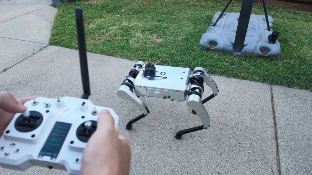
The goal is not to run fast on the first attempt. The goal is to create a repeatable test procedure. After every run, record:
- Battery percentage and voltage changes.
- Actuator temperature and warnings.
- Jetson CPU/GPU load and temperature.
- ROS 2 node timeouts or dropped messages.
- CAN bus communication errors.
- Which motion most easily triggers instability.
Only with enough test records can you responsibly tune policies, change mechanics, adjust parameters, or optimize gait behavior.
Key Hardware Notes
Actuator Direction
Actuator direction is one of the most common bring-up problems. Even if the ID is correct, a reversed direction makes the policy output the wrong physical motion. Each joint should be tested independently with a small command.
Thread Locker
Use a small amount of thread locker around actuators, linkages, support posts, and frame joints. Do not overuse it, or later maintenance becomes difficult. Do not skip it either, because long-duration locomotion can loosen fasteners.
Cable Routing
Cables should not sit close to rotating joints, pass through crush zones, or rely on connectors to absorb pulling force. CAN, power, USB, and antenna cables all need fixed routing points.
Emergency Stop
Emergency stop is not decorative. Validate it before the first actuator enable. If a quadruped fails during standing, human reaction time is usually not enough.
CAN Bus
CAN bus issues often appear as intermittent motion loss or one joint dropping offline. Check bitrate, termination, cable length, loose connectors, USB-CAN driver behavior, and device permissions.
LoRa and Remote Control
LoRa is useful for longer-range operation in open areas. For indoor or short-range bring-up, a local remote controller or ROS 2 control interface is usually more convenient. Do not assume the long-range link is stable in a closed or cluttered environment.
Jetson Thermal and Power
Jetson runs ROS 2, drivers, and the RL policy at the same time, so power and cooling matter. Poor cooling can cause throttling. Unstable power can cause random reboots or peripheral dropouts.
Debugging Notes
| Problem | Check First |
|---|---|
| No power-on | Battery, power button, emergency stop, BMS, main board input |
| Cannot log into Jetson | First boot via HDMI, IP address, Ethernet/Wi-Fi, SSH service |
| SSH disconnects often | Wi-Fi driver, power stability, Jetson temperature, network quality |
| No IMU data | USB connection, device node, permissions, driver, ROS 2 topic |
| CAN device unavailable | USB-CAN driver, enumeration, bitrate, permissions |
| One actuator does not respond | ID, power, CAN wiring, control mode, parameter reload |
| Shaking during standing | Zero position, direction, IMU attitude, leg interference, control gains |
| Wrong forward direction | Body coordinate frame, remote mapping, joint direction, policy input |
| Turning behaves incorrectly | Left/right leg mapping, yaw command direction, IMU frame |
| Outdoor test is unstable | Ground friction, grass resistance, battery level, communication distance, actuator temperature |
Do not change multiple variables at once. Quadruped failure chains are long. If you change wiring, ID mapping, policy, and remote mapping simultaneously, it becomes hard to know which change actually fixed the issue.
Final Result
After completing the process above, NavBot-D1 should have the following capabilities:
- Jetson can be maintained remotely through SSH.
- The ROS 2 runtime stack starts reliably.
- IMU and USB-CAN can be detected and tested.
- All 12 actuator IDs, directions, and zero positions are traceable.
- The robot can power on, stand, and switch into RL locomotion mode safely.
- Remote input can trigger forward, backward, turning, and faster movement.
More importantly, the developer now has an extensible quadruped platform. The next steps can include local development tooling, simulation, reinforcement-learning training, perception modules, navigation modules, and remote operation systems.
Reproduction Suggestions
If you plan to reproduce or extend NavBot-D1, I recommend the following priorities:
- Reproduce bring-up first, do not modify algorithms first Stabilize the original hardware and software stack before tuning policies.
- Test one leg before the full robot If possible, use a single leg or single actuator to validate ID, direction, mode, and CAN communication.
- Start indoors and short-range before outdoor long-range tests Outdoor testing adds ground conditions, communication range, battery level, and safety risks. It is not ideal for first bring-up.
- Keep logs for every test When a robot falls or shakes, logs are more reliable than intuition.
- Separate mechanical changes from software changes Changing leg geometry, wiring, battery, or policy parameters should be recorded separately.
- Put safety before features Emergency stop, mechanical limits, low-speed testing, and power management are not optional extras. They are the foundation of dynamic robot development.
NavBot-D1 matters because it provides a sufficiently complete real robot platform. It has mechanical complexity, onboard compute, and RL locomotion. It supports hardware integration, software control, and simulation research. For robotics developers, this kind of platform is ideal for building end-to-end engineering capability across CAD, BOM, wiring, ROS 2, CAN, calibration, and policy deployment.
Appendix
Video Source: https://youtu.be/Raj1pK31hU4, or watch it right here.



Leave a Reply