Your cart is currently empty!


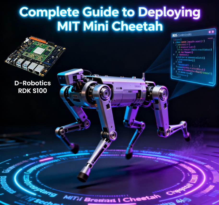
This article aims to systematically analyze the technical architecture and implementation details of the MIT Cheetah robot. The content is compiled from publicly available materials and combined with personal practical understanding, intended to provide reference for relevant technical developers.
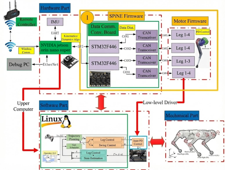
MIT Cheetah System Architecture Diagram:
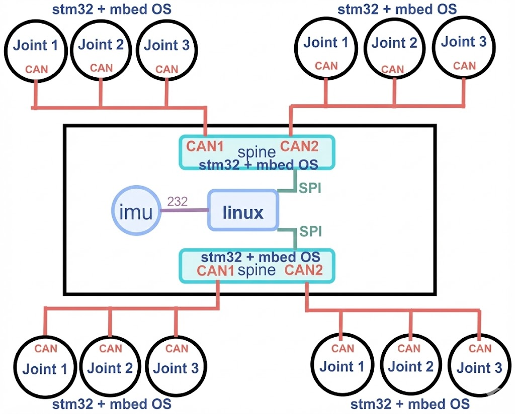
Data Communication Protocol Architecture Diagram:
1. Introduction to mbedOS
Developers who first encounter the MIT Cheetah project may notice that the codebase on GitHub is relatively small, and the compilation method differs from conventional projects. This is primarily because the project uses mbedOS as its underlying development framework.
The hardware modules of MIT Cheetah have relatively small code volumes. For example, the SPIne module primarily focuses on data interaction processing, while underlying hardware drivers and other basic functions are provided by mbedOS.
mbedOS is a complete software solution developed by ARM for IoT applications, and it is an embedded open-source ecosystem targeting ARM Cortex-M series processors. For more information, please visit the mbedOS official website.
The following example demonstrates how to initialize the SPI interface in the SPIne module:
void init_spi(void){
    SPISlave *spi = new SPISlave(PA_7, PA_6, PA_5, PA_4);
    spi->format(16, 0);         // 16bit
    spi->frequency(12000000);  // 12M
    spi->reply(0x0);
    cs.fall(&spi_isr);
    printf("done\n\r");
}
The following is a typical application example of CAN bus communication:
#include "mbed.h"

DigitalOut myled(D8);
CAN can1(PD_0, PD_1,500000);
int main() {
     CANMessage msg;
    while(1) {
   if(can1.read(msg)) {
            printf("Message received:id=%d,type=%d,%d\n", msg.id,msg.type,msg.data[0]);
            myled = !myled;
    }
    }
}
2. MIT Cheetah Open Source Resources
The following are open source resource links related to the MIT Cheetah project:
Hardware Related:
▪️ Motor Controller Hardware: https://github.com/bgkatz/3phase_integrated
▪️ SPIne Hardware: https://github.com/bgkatz/SPIne
Software Related:
▪️ Motor Controller Software: https://os.mbed.com/users/benkatz/code/Hobbyking_Cheetah_Compact_DRV8323/
▪️ SPIne Software: https://os.mbed.com/users/benkatz/code/SPIne/
▪️ Linux Control Code (Cheetah Mini): https://github.com/mit-biomimetics/Cheetah-Software
3. MIT Mini Cheetah Robot System
3.1 Simulation Environment Configuration and Usage
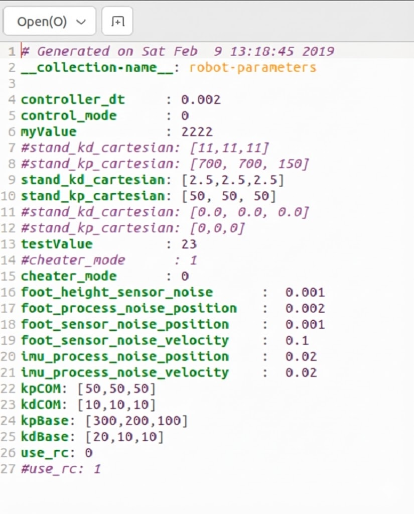
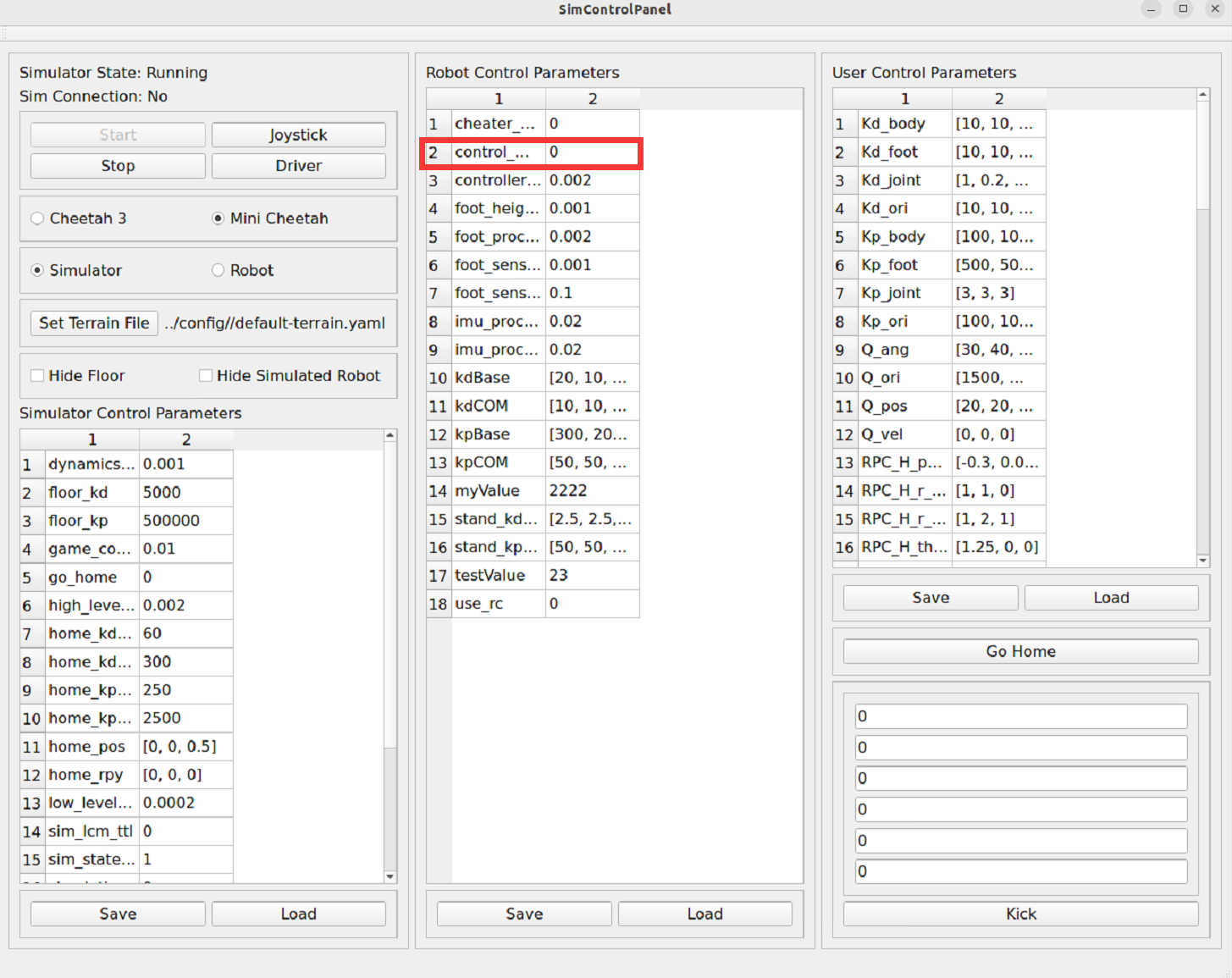
After compilation is complete, you need to configure the simulation environment parameters. Navigate to the config directory under the MIT main folder, open the mini-cheetah-defaults.yaml file, set control_mode and cheater_mode to 1, and set use_rc to 0. After configuration, save and exit, as shown in the following figure:
Next, start the robot simulation environment. It is recommended to connect a game controller before starting (optional, for subsequent control). Navigate to the build directory under the MIT main folder (Note: directly entering the sim subdirectory may prevent the simulation from starting, so execute in the build directory), right-click in a blank area and select “Open in Terminal”, then execute the following command:
./sim/sim
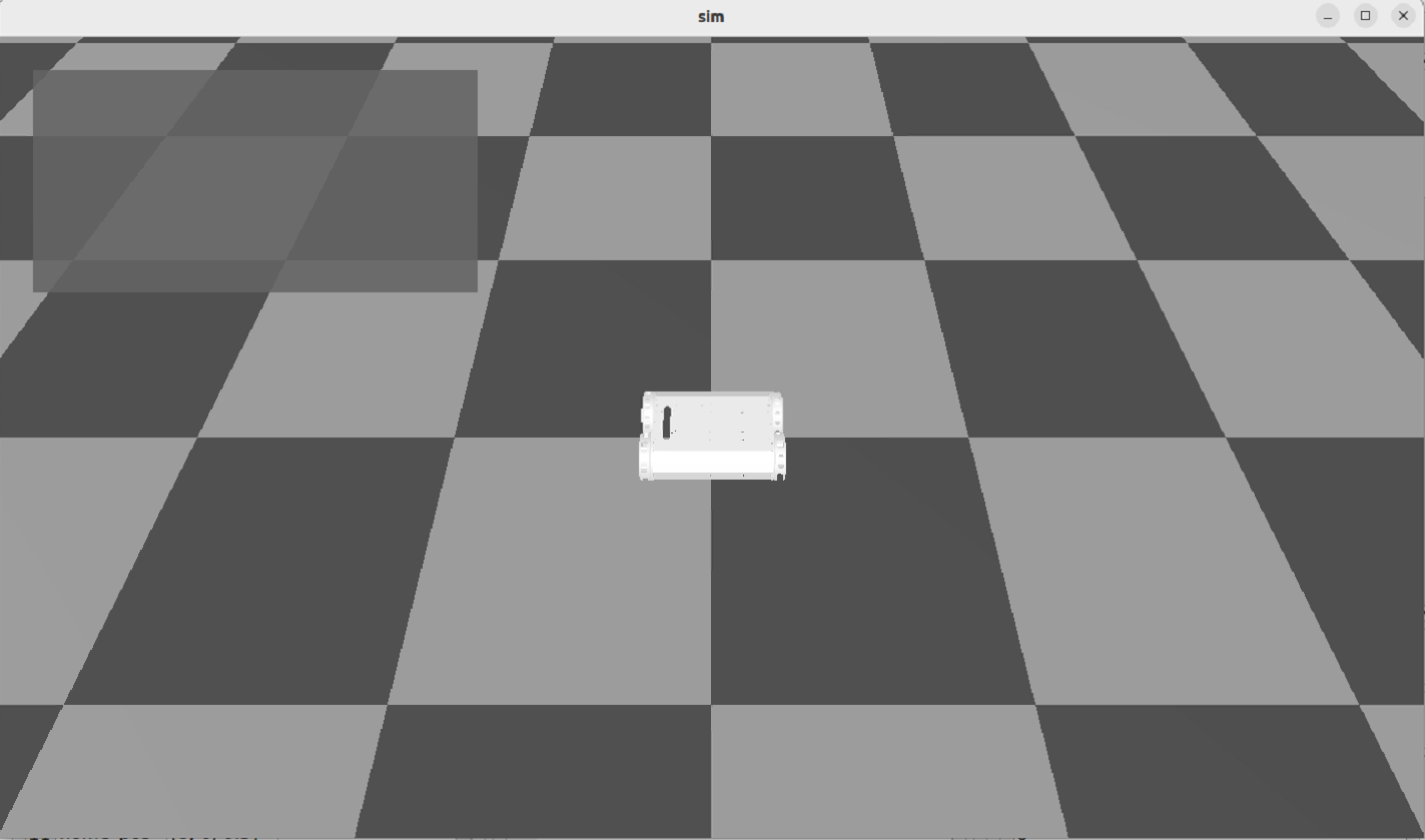
After execution, the robot simulation control interface will be displayed, as shown in the following figure:
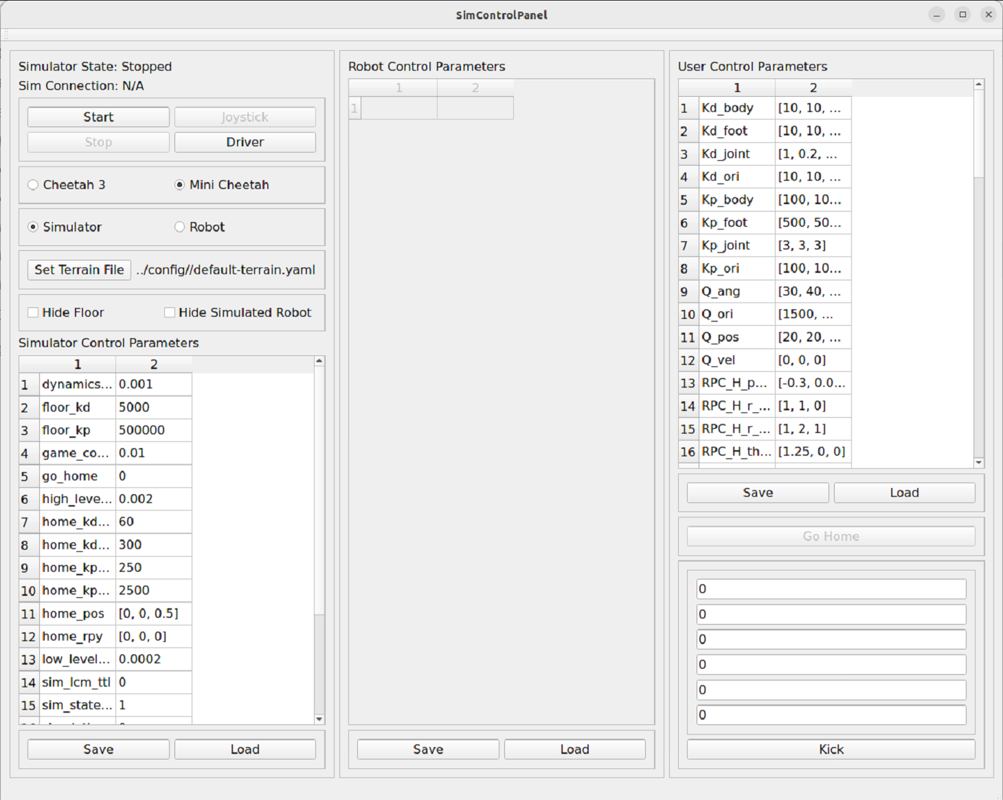
In the control interface, click “Mini Cheetah” and “Simulator” in sequence, then click the “Start” button to launch the robot simulation interface, as shown in the following figure:
Next, start the robot controller. Navigate to the build/user/MIT_Controller directory under the MIT main folder, right-click in a blank area and select “Open in Terminal”, then execute the following command:
./mit_ctrl m s
Here, mit_ctrl is the compiled executable file, parameter m represents the mini cheetah model, and parameter s represents simulate (simulation mode). After execution, the robot in the simulation should be able to stand up. At this point, switch to the simulation control interface and change the control_mode value to 4. You can observe that the robot in the simulation switches to trot (trotting gait), as shown in the following figure:
At this point, you can control the robot’s movement speed through the game controller’s joystick. Readers can explore different control modes on their own. The following describes the implementation method for backflip operation:
1. Change the control_mode value in the simulation control interface to 3, and the robot will enter a standing state
2. Change the control_mode value to 9, and the robot will perform a backflip action
3. After the backflip is complete, change the control_mode value to 3 again, then change it to 9 to repeat the backflip
Note: If the robot falls during operation, you can click the “Go Home” button in the simulation control interface to restore the robot to its initial position. If it cannot be restored, you need to restart the simulation and controller.
3.2 Real Robot and Simulation Combined Usage
When running the real robot, you need to start both the simulation interface and the controller program:
# Terminal 1: Start simulation interface
./sim/sim
# Terminal 2: Start controller (real robot mode)
./mit_ctrl m r f
Here, parameter r represents robot (real robot mode), and parameter f represents other configuration options.
4. Computer Board Selection
The original MIT Mini Cheetah system runs on UP Board, which uses a 4-core Intel Atom x5-Z8350 processor, equipped with 4GB RAM, peak power consumption of approximately 5W, based on x86 architecture.
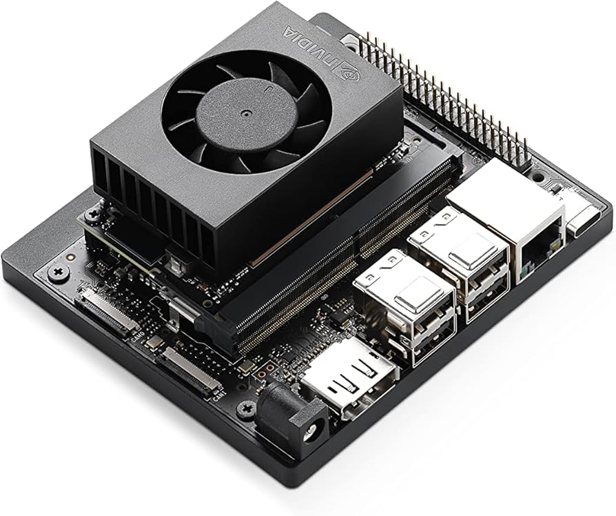
UP Board has relatively few applications in the Chinese market. More common choices include Raspberry Pi and NVIDIA Jetson Nano. Among them, Raspberry Pi is more oriented towards general embedded applications, while Jetson Nano is more suitable for image processing and AI model deployment.
The solution described in this article uses Jetson Nano as the computing platform, running Ubuntu 22 system, equipped with a 6-core ARM Cortex-A78AE v8.2 64-bit processor (ARM architecture).
It should be noted that for the SPIne board, the GPIO interfaces of UP Board and Jetson Nano are compatible, which provides convenience for platform migration.
4.1 Jetson Nano Software Environment Configuration
The development environment used in this article is Ubuntu 20.04.
4.1.1 Download Cheetah-Software Source Code
git clone https://github.com/fuwei007/NavBot-EG02
4.1.2 Install Third-Party Dependency Libraries
sudo apt-get update
sudo apt -y install cmake gcc build-essential
sudo apt-get -y install openjdk-11-jdk
sudo apt -y install liblcm-dev
sudo apt-get -y install libeigen3-dev
sudo apt-get -y install mesa-common-dev
sudo apt -y install libgl1-mesa-dev
sudo apt -y install libglu1-mesa-dev
sudo apt-get -y install freeglut3-dev
sudo apt-get -y install libblas-dev liblapack-dev
sudo apt-get -y install libopenblas-dev
sudo apt install -y coinor-libipopt-dev gfortran libglib2.0-dev
sudo apt install -y openjdk-8-jdk
4.1.3 Install Qt
Method 1: Source Code Compilation Installation
Download Qt 5.14.2 version: Qt 5.14.2 Download Link
After downloading, navigate to the directory where the file is located, right-click the Qt installation file, select “Properties” → “Permissions”, and check “Allow executing file as program”. Then open a terminal in that directory and execute the following command to start the Qt installation program (Note: the filename in the command should match the actual downloaded filename):
./qt-opensource-linux-x64-5.14.2.run
The installation process is similar to installing programs on Windows, just follow the wizard to complete the installation.
Method 2: Install Using apt Package Manager
sudo apt install -y libqt5 libqt5gamepad5
4.1.4 Install LCM
LCM (Lightweight Communications and Marshalling) is a library for message passing and marshalling.
Download LCM 1.4.0 installation package: LCM v1.4.0 Download Link
After downloading, extract the archive, navigate to the extracted folder, right-click in a blank area and select “Open in Terminal”, then execute the following commands in sequence (it is recommended to execute them one by one):
mkdir build
cd build
cmake ..
make
sudo make install
sudo ldconfig
4.1.5 Install Eigen 3.3.6
Eigen is a C++ template library for linear algebra, matrix and vector operations. Based on practical experience, Eigen 3.3.6 version has good compatibility with the MIT Cheetah project, and other versions may have compatibility issues. It is recommended to use version 3.3.6.
Download Eigen 3.3.6: Eigen 3.3.6 Download Link
After downloading, extract the archive, navigate to the extracted folder, right-click in a blank area and select “Open in Terminal”, then execute the following commands in sequence (it is recommended to execute them one by one):
mkdir build
cd build
cmake ..
make
sudo make install
sudo ldconfig
4.1.6 Modify Source Code Configuration
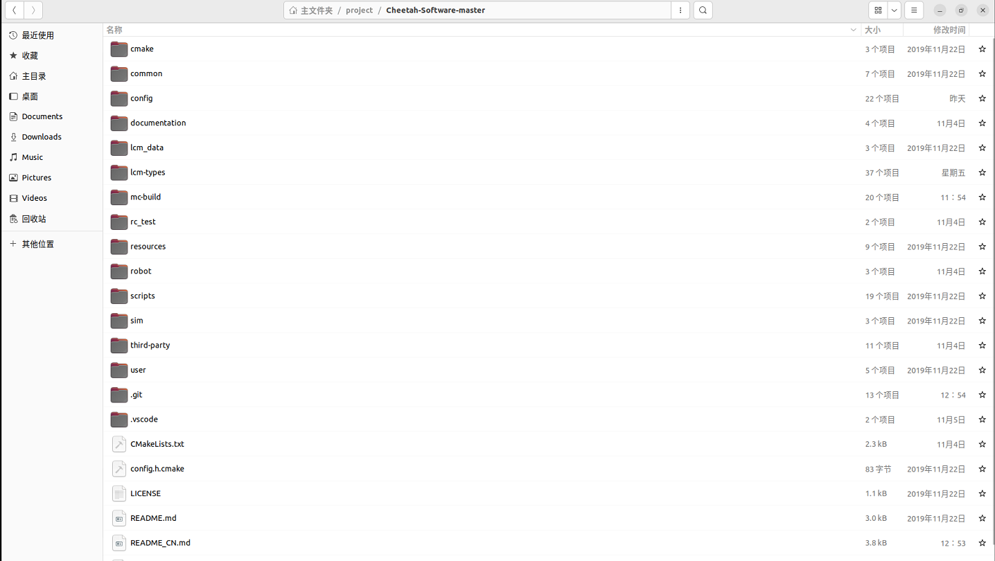
Navigate to the Cheetah-Software main folder (hereinafter referred to as MIT main folder). The folder structure is shown in the following figure:
The following modifications need to be made:
Step1: Modify Branch Name in CMakeLists.txt
Open the common/CMakeLists.txt file under the MIT main folder, and change master at the position marked in the figure below to main. At the same time, since pulling the googletest library from GitHub is slow in China, it is recommended to switch to the Gitee mirror source.
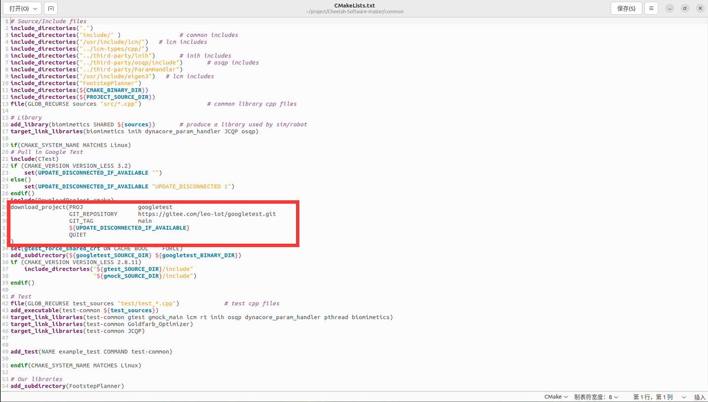
After modification, save and exit.
step2: Modify Eigen3 and LCM Header File Paths
Modify the header file include paths according to the actual installation path. If Eigen3 and LCM are installed in the /usr/include directory (rather than the default /usr/local/include in the source code), you need to modify the include paths in all related files.
Search and replace the following content:
Original Path:
include_directories("/usr/local/include/lcm/")
include_directories("/usr/local/include/eigen3")
Replace with:
include_directories("/usr/include/lcm/")
include_directories("/usr/include/eigen3")
List of Files to Modify:
Cheetah-Software-master/common/CMakeLists.txt
Cheetah-Software-master/rc_test/CMakeLists.txt
Cheetah-Software-master/robot/CMakeLists.txt
Cheetah-Software-master/sim/CMakeLists.txt
Cheetah-Software-master/user/MIT_Controller/CMakeLists.txt
step3: Modify Qt Path Configuration
Modify the file Cheetah-Software/scripts/find_qt_path.sh, comment out the default Qt path:
#printf "${HOME}/Qt/${QT_VER}/gcc_64/"Then add your own Qt installation path, as shown in the following figure:
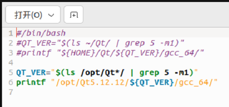
Note: The path after printf should include the bin directory.
step4: Fix Serial Port Header File Missing Issue
Modify the file Cheetah-Software/robot/src/rt/rt_serial.cpp:
▪️ Comment out #include <stropts.h>
▪️ Add #include <sys/ioctl.h> before #include <asm/termios.h>
Then fix the redefinition: vim /usr/include/asm-generic/termios.h Add #ifndef _SYS_IOCTL_H and #endif at the following position:
#ifndef _SYS_IOCTL_H
struct winsize {
        unsigned short ws_row;
        unsigned short ws_col;
        unsigned short ws_xpixel;
        unsigned short ws_ypixel;
};

#define NCC 8
struct termio {
        unsigned short c_iflag;         /* input mode flags */
        unsigned short c_oflag;         /* output mode flags */
        unsigned short c_cflag;         /* control mode flags */
        unsigned short c_lflag;         /* local mode flags */
        unsigned char c_line;           /* line discipline */
        unsigned char c_cc[NCC];        /* control characters */
};
#endif
4.1.7 Compile Program
It is recommended to build inside the mc-build folder at the project root directory :
cd mc-build
rm CMakeCache.txt  # Clean up old configuration (if present)

# Configure the project
# -DMINI_CHEETAH_BUILD=TRUE: build the Mini Cheetah version
# -DJCQP_USE_AVX2=OFF: disable x86 AVX2 optimizations, so it suits ARM architectures (e.g., Jetson Nano / NX)
cmake -DMINI_CHEETAH_BUILD=TRUE -DJCQP_USE_AVX2=OFF ..

# Build (adjust the -j parameter according to the number of CPU cores)
make -j4
Notes:
▪️ File deletion related errors that appear when executing ./make_types.sh can be ignored
▪️ The cmake command may get stuck at a certain step (usually related to Google services), which is a network issue and requires patience
▪️ make -j$(nproc) will automatically use all available CPU cores for parallel compilation. If your system doesn’t support this, you can use the make command instead, but compilation speed will be slower
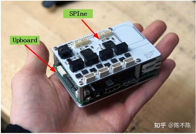
5. SPIne Data Communication Conversion Board
SPIne is a key communication conversion module in the MIT Cheetah system, responsible for data conversion and transmission between the computer board and motor controllers.
Open Source Code Download Address: SPIne Firmware
5.1 Communication Rate Configuration
1. CAN Bus Communication: The communication rate of each CAN bus is configured to 1Mbps. SPIne uses two STM32 microcontrollers because a single CAN bus does not have sufficient bandwidth to support all motor communication requirements. Each STM32 provides two CAN buses, and each CAN bus is responsible for three motors’ communication to achieve a 1000Hz communication frequency. If a single CAN bus is responsible for two legs (six motors), it cannot achieve the required communication frequency.
2. SPI Communication: The SPI communication clock frequency between SPIne and the computer board is 12MHz, with a communication frequency of 1000Hz.
5.2 Communication Data Format
CAN Format: Each frame is 8 bytes.
SPIne → Joint Motor Controller (Command, 8 bytes):
▪️ Position command: 16bit
▪️ Velocity command: 12bit
▪️ Kp (position gain): 12bit
▪️ Kd (velocity gain): 12bit
▪️ Feedforward torque: 12bit
Joint Motor Controller → SPIne (Feedback, 5 bytes):
▪️ Position information: 16bit
▪️ Velocity information: 12bit
▪️ Current (torque): 12bit
PC → SPIne (Command, 132 bytes): Contains 33 data items: position commands, velocity commands, Kp, Kd, and feedforward torque for 6 joints, plus two flags and one checksum.
5.3 Code Architecture
The code structure of the SPIne firmware is shown in the following figure:
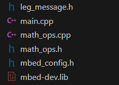
Main Module Descriptions:
▪️ leg_message: Responsible for data downlink and uplink encapsulation between UPboard and SPIne, as well as data encapsulation between SPIne and motor controllers
▪️ math_ops: Provides mathematical operation functions
▪️ main: Program main entry function
5.4 Communication Protocol Details
UPboard Computer Board <—-> SPIne Firmware
SPI Communication Protocol:
UPboard Computer Board---->SPIne Firmware

// 60 bytes
// 30 16-bit words
struct spi_data_t
{
    float q_abad[2];
    float q_hip[2];
    float q_knee[2];
    float qd_abad[2];
    float qd_hip[2];
    float qd_knee[2];
    int32_t flags[2];
    int32_t checksum;
};

UPboard Computer Board<----SPIne Firmware

// 132 bytes
// 66 16-bit words
struct spi_command_t
{
    float q_des_abad[2];
    float q_des_hip[2];
    float q_des_knee[2];
    float qd_des_abad[2];
    float qd_des_hip[2];
    float qd_des_knee[2];
    float kp_abad[2];
    float kp_hip[2];
    float kp_knee[2];
    float kd_abad[2];
    float kd_hip[2];
    float kd_knee[2];
    float tau_abad_ff[2];
    float tau_hip_ff[2];
    float tau_knee_ff[2];
    int32_t flags[2];
    int32_t checksum;
};
SPIne Firmware <—-> Motor Controller
CAN Communication Protocol:
SPIne Firmware---->Motor Controller

/// CAN Command Packet Structure ///
/// 16 bit position command, between -4*pi and 4*pi
/// 12 bit velocity command, between -30 and + 30 rad/s
/// 12 bit kp, between 0 and 500 N-m/rad
/// 12 bit kd, between 0 and 100 N-m*s/rad
/// 12 bit feed forward torque, between -18 and 18 N-m
/// CAN Packet is 8 8-bit words
/// Formatted as follows.  For each quantity, bit 0 is LSB
/// 0: [position[15-8]]
/// 1: [position[7-0]]
/// 2: [velocity[11-4]]
/// 3: [velocity[3-0], kp[11-8]]
/// 4: [kp[7-0]]
/// 5: [kd[11-4]]
/// 6: [kd[3-0], torque[11-8]]
/// 7: [torque[7-0]]


SPIne Firmware<----Motor Controller

/// CAN Reply Packet Structure
/// 16 bit position, between -4*pi and 4*pi
/// 12 bit velocity, between -30 and + 30 rad/s
/// 12 bit current, between -40 and 40;
/// CAN Packet is 5 8-bit words
/// Formatted as follows.  For each quantity, bit 0 is LSB
/// 0: [position[15-8]]
/// 1: [position[7-0]]
/// 2: [velocity[11-4]]
/// 3: [velocity[3-0], current[11-8]]
/// 4: [current[7-0]]
5.5 SPIne Firmware SPI Communication Implementation Analysis
5.5.1 Data Buffer Definition
// Receive and transmit byte count
#define RX_LEN 66
#define TX_LEN 66
// SPI data buffer
uint16_t rx_buff[RX_LEN];
uint16_t tx_buff[TX_LEN];
5.5.2 SPIne and UPboard Data Encapsulation Structure
spi_data_t spi_data; // data from spine to up
spi_command_t spi_command; // data from up to spine

// 60 bytes
// 30 16-bit words
struct spi_data_t
{    //position
    float q_abad[2];
    float q_hip[2];
    float q_knee[2];
     //velocity
    float qd_abad[2];
    float qd_hip[2];
    float qd_knee[2];
    //flags and checksum
    int32_t flags[2];
    int32_t checksum;
};

// 132 bytes
// 66 16-bit words
struct spi_command_t
{
    //position
    float q_des_abad[2];
    float q_des_hip[2];
    float q_des_knee[2];
   //velocity
    float qd_des_abad[2];
    float qd_des_hip[2];
    float qd_des_knee[2];
    //gain KP
    float kp_abad[2];
    float kp_hip[2];
    float kp_knee[2];
    //gain KD
    float kd_abad[2];
    float kd_hip[2];
    float kd_knee[2];
     //feedforward torque
    float tau_abad_ff[2];
    float tau_hip_ff[2];
    float tau_knee_ff[2];
    //flags and checksum
    int32_t flags[2];
    int32_t checksum;
};
5.5.3 SPI Interrupt Service Routine
The SPI interrupt service routine is responsible for handling SPI communication data transmission and reception:
void spi_isr(void)
{
    GPIOC->ODR |= (1 << 8);
    GPIOC->ODR &= ~(1 << 8);
    int bytecount = 0;
    SPI1->DR = tx_buff[0];
    while(cs == 0) {
        if(SPI1->SR&0x1) {
            rx_buff[bytecount] = SPI1->DR;//data reception
            bytecount++;
            if(bytecount<TX_LEN) {
                SPI1->DR = tx_buff[bytecount];//data transmission
            }
        }
    }
    // after reading, save into spi_command
    //After reading data, save it in the spi_command structure
    // should probably check checksum first!
    //data checksum
    uint32_t calc_checksum = xor_checksum((uint32_t*)rx_buff,32);
    for(int i = 0; i < CMD_LEN; i++)
    {
        ((uint16_t*)(&spi_command))[i] = rx_buff[i];//spi_command data assignment
    }

    // run control, which fills in tx_buff for the next iteration
    //
    if(calc_checksum != spi_command.checksum){
        spi_data.flags[1] = 0xdead;}

    //test_control();
    //spi_data.q_abad[0] = 12.0f;
    control();//Assign the state information received from the robot motor controller to tx_buff and send it to UPboard via SPI
    PackAll();//Write the control data received from UPboard into CAN buffer
    WriteAll();//Send CAN buffer data to leg motor controllers via CAN
}
5.5.4 Control Function Implementation
The control() function is responsible for assigning the state information received from the motor controller to tx_buff and sending it to UPboard via SPI:
void control()
{
    //Enter motor mode
    if(((spi_command.flags[0]&0x1)==1)  && (enabled==0)){
        enabled = 1;
        EnterMotorMode(&a1_can);
        can1.write(a1_can);
        EnterMotorMode(&a2_can);
        can2.write(a2_can);
        EnterMotorMode(&k1_can);
        can1.write(k1_can);
        EnterMotorMode(&k2_can);
        can2.write(k2_can);
        EnterMotorMode(&h1_can);
        can1.write(h1_can);
        EnterMotorMode(&h2_can);
        can2.write(h2_can);
        printf("e\n\r");
        return;
    }
      //Exit motor mode
    else if((((spi_command.flags[0]&0x1))==0)  && (enabled==1)){
         enabled = 0;
        ExitMotorMode(&a1_can);
        can1.write(a1_can);
        ExitMotorMode(&a2_can);
        can2.write(a2_can);
        ExitMotorMode(&h1_can);
        can1.write(h1_can);
        ExitMotorMode(&h2_can);
        can2.write(h2_can);
        ExitMotorMode(&k1_can);
        can1.write(k1_can);
        ExitMotorMode(&k2_can);
        can2.write(k2_can);
        printf("x\n\r");
        return;
        }
    //Assign the state information received from the motor controller to spi_data (send to UPboard)
    spi_data.q_abad[0] = l1_state.a.p;
    spi_data.q_hip[0] = l1_state.h.p;
    spi_data.q_knee[0] = l1_state.k.p;
    spi_data.qd_abad[0] = l1_state.a.v;
    spi_data.qd_hip[0] = l1_state.h.v;
    spi_data.qd_knee[0] = l1_state.k.v;

    spi_data.q_abad[1] = l2_state.a.p;
    spi_data.q_hip[1] = l2_state.h.p;
    spi_data.q_knee[1] = l2_state.k.p;
    spi_data.qd_abad[1] = l2_state.a.v;
    spi_data.qd_hip[1] = l2_state.h.v;
    spi_data.qd_knee[1] = l2_state.k.v;

    if(estop==0){//Emergency stop
        //printf("estopped!!!!\n\r");
        memset(&l1_control, 0, sizeof(l1_control));
        memset(&l2_control, 0, sizeof(l2_control));
        spi_data.flags[0] = 0xdead;
        spi_data.flags[1] = 0xdead;
        led = 1;
        }

    else{//Running state, assign the spi_command data received from UPboard to l1_control (send to motor controller)
        led = 0;

        memset(&l1_control, 0, sizeof(l1_control));
        memset(&l2_control, 0, sizeof(l2_control));

        l1_control.a.p_des = spi_command.q_des_abad[0];
        l1_control.a.v_des  = spi_command.qd_des_abad[0];
        l1_control.a.kp = spi_command.kp_abad[0];
        l1_control.a.kd = spi_command.kd_abad[0];
        l1_control.a.t_ff = spi_command.tau_abad_ff[0];

        l1_control.h.p_des = spi_command.q_des_hip[0];
        l1_control.h.v_des  = spi_command.qd_des_hip[0];
        l1_control.h.kp = spi_command.kp_hip[0];
        l1_control.h.kd = spi_command.kd_hip[0];
        l1_control.h.t_ff = spi_command.tau_hip_ff[0];

        l1_control.k.p_des = spi_command.q_des_knee[0];
        l1_control.k.v_des  = spi_command.qd_des_knee[0];
        l1_control.k.kp = spi_command.kp_knee[0];
        l1_control.k.kd = spi_command.kd_knee[0];
        l1_control.k.t_ff = spi_command.tau_knee_ff[0];

        l2_control.a.p_des = spi_command.q_des_abad[1];
        l2_control.a.v_des  = spi_command.qd_des_abad[1];
        l2_control.a.kp = spi_command.kp_abad[1];
        l2_control.a.kd = spi_command.kd_abad[1];
        l2_control.a.t_ff = spi_command.tau_abad_ff[1];

        l2_control.h.p_des = spi_command.q_des_hip[1];
        l2_control.h.v_des  = spi_command.qd_des_hip[1];
        l2_control.h.kp = spi_command.kp_hip[1];
        l2_control.h.kd = spi_command.kd_hip[1];
        l2_control.h.t_ff = spi_command.tau_hip_ff[1];

        l2_control.k.p_des = spi_command.q_des_knee[1];
        l2_control.k.v_des  = spi_command.qd_des_knee[1];
        l2_control.k.kp = spi_command.kp_knee[1];
        l2_control.k.kd = spi_command.kd_knee[1];
        l2_control.k.t_ff = spi_command.tau_knee_ff[1];

        //Soft stop program to prevent stopping too abruptly
        spi_data.flags[0] = 0;
        spi_data.flags[1] = 0;
        spi_data.flags[0] |= softstop_joint(l1_state.a, &l1_control.a, A_LIM_P, A_LIM_N);
        spi_data.flags[0] |= (softstop_joint(l1_state.h, &l1_control.h, H_LIM_P, H_LIM_N))<<1;
        //spi_data.flags[0] |= (softstop_joint(l1_state.k, &l1_control.k, K_LIM_P, K_LIM_N))<<2;
        spi_data.flags[1] |= softstop_joint(l2_state.a, &l2_control.a, A_LIM_P, A_LIM_N);
        spi_data.flags[1] |= (softstop_joint(l2_state.h, &l2_control.h, H_LIM_P, H_LIM_N))<<1;
        //spi_data.flags[1] |= (softstop_joint(l2_state.k, &l2_control.k, K_LIM_P, K_LIM_N))<<2;
    }
    spi_data.checksum = xor_checksum((uint32_t*)&spi_data,14);
    for(int i = 0; i < DATA_LEN; i++){
        tx_buff[i] = ((uint16_t*)(&spi_data))[i];}

}
5.5.5 Soft Stop Program Implementation
The soft stop program is used to prevent overly abrupt movements when joint motion exceeds limits:
int softstop_joint(joint_state state, joint_control * control, float limit_p, float limit_n){
    if((state.p)>=limit_p){
        //control->p_des = limit_p;
        control->v_des = 0.0f;
        control->kp = 0;
        control->kd = KD_SOFTSTOP;
        control->t_ff += KP_SOFTSTOP*(limit_p - state.p);
        return 1;
    }
    else if((state.p)<=limit_n){
        //control->p_des = limit_n;
        control->v_des = 0.0f;
        control->kp = 0;
        control->kd = KD_SOFTSTOP;
        control->t_ff += KP_SOFTSTOP*(limit_n - state.p);
        return 1;
    }
    return 0;

    }
5.5.6 Data Packing Function
The PackAll() function is responsible for packing the control data received from UPboard into the CAN buffer:
//l1_control encapsulates the data received from UPboard, i.e., encapsulates spi_command
struct leg_control{
    joint_control a, h, k;
    }
struct joint_control{
    float p_des, v_des, kp, kd, t_ff;//position, velocity, KP, KD, torque t_ff
    };
void PackAll(){
    pack_cmd(&a1_can, l1_control.a); //Left leg 1 ankle motor
    pack_cmd(&a2_can, l2_control.a); //Left leg 2 ankle motor
    pack_cmd(&h1_can, l1_control.h); //Left leg 1 hip motor
    pack_cmd(&h2_can, l2_control.h); //Left leg 2 hip motor
    pack_cmd(&k1_can, l1_control.k); //Left leg 1 Knee motor
    pack_cmd(&k2_can, l2_control.k); //Right leg 2 Knee motor

    }
5.5.7 CAN Data Packing Function
The pack_cmd() function parses the control information sent from UPboard and packs it into the CAN buffer, ready to be sent to the motor controller:
/// CAN Command Packet Structure ///
/// 16 bit position command, between -4*pi and 4*pi
/// 12 bit velocity command, between -30 and + 30 rad/s
/// 12 bit kp, between 0 and 500 N-m/rad
/// 12 bit kd, between 0 and 100 N-m*s/rad
/// 12 bit feed forward torque, between -18 and 18 N-m
/// CAN Packet is 8 8-bit words
/// Formatted as follows.  For each quantity, bit 0 is LSB
/// 0: [position[15-8]]
/// 1: [position[7-0]]
/// 2: [velocity[11-4]]
/// 3: [velocity[3-0], kp[11-8]]
/// 4: [kp[7-0]]
/// 5: [kd[11-4]]
/// 6: [kd[3-0], torque[11-8]]
/// 7: [torque[7-0]]

void pack_cmd(CANMessage * msg, joint_control joint){

     /// limit data to be within bounds ///
     float p_des = fminf(fmaxf(P_MIN, joint.p_des), P_MAX);
     float v_des = fminf(fmaxf(V_MIN, joint.v_des), V_MAX);
     float kp = fminf(fmaxf(KP_MIN, joint.kp), KP_MAX);
     float kd = fminf(fmaxf(KD_MIN, joint.kd), KD_MAX);
     float t_ff = fminf(fmaxf(T_MIN, joint.t_ff), T_MAX);
     /// convert floats to unsigned ints ///
     uint16_t p_int = float_to_uint(p_des, P_MIN, P_MAX, 16);
     uint16_t v_int = float_to_uint(v_des, V_MIN, V_MAX, 12);
     uint16_t kp_int = float_to_uint(kp, KP_MIN, KP_MAX, 12);
     uint16_t kd_int = float_to_uint(kd, KD_MIN, KD_MAX, 12);
     uint16_t t_int = float_to_uint(t_ff, T_MIN, T_MAX, 12);
     /// pack ints into the can buffer ///
     msg->data[0] = p_int>>8;
     msg->data[1] = p_int&0xFF;
     msg->data[2] = v_int>>4;
     msg->data[3] = ((v_int&0xF)<<4)|(kp_int>>8);
     msg->data[4] = kp_int&0xFF;
     msg->data[5] = kd_int>>4;
     msg->data[6] = ((kd_int&0xF)<<4)|(t_int>>8);
     msg->data[7] = t_int&0xff;
     }
5.5.8 CAN Data Transmission Function
The WriteAll() function sends control data for all motors via the CAN bus:
void WriteAll(){
    //toggle = 1;
    can1.write(a1_can);
    wait(.00002);
    can2.write(a2_can);
    wait(.00002);
    can1.write(h1_can);
    wait(.00002);
    can2.write(h2_can);
    wait(.00002);
    can1.write(k1_can);
    wait(.00002);
    can2.write(k2_can);
    wait(.00002);
    //toggle = 0;
    }
5.6 SPIne Firmware and PC Serial Communication
SPIne communicates with the PC through serial port for debugging and manual control:
void serial_isr(){
     /// handle keyboard commands from the serial terminal ///
     while(pc.readable()){
        char c = pc.getc();
        //led = !led;
        switch(c){
            case(27):
                //loop.detach();
                printf("\n\r exiting motor mode \n\r");
                ExitMotorMode(&a1_can);
                ExitMotorMode(&a2_can);
                ExitMotorMode(&h1_can);
                ExitMotorMode(&h2_can);
                ExitMotorMode(&k1_can);
                ExitMotorMode(&k2_can);
                enabled = 0;
                break;
            case('m'):
                printf("\n\r entering motor mode \n\r");
                EnterMotorMode(&a1_can);
                EnterMotorMode(&a2_can);
                EnterMotorMode(&h1_can);
                EnterMotorMode(&h2_can);
                EnterMotorMode(&k1_can);
                EnterMotorMode(&k2_can);
                wait(.5);
                enabled = 1;
                //loop.attach(&sendCMD, .001);
                break;
            case('s'):
                printf("\n\r standing \n\r");
                counter2 = 0;
                is_standing = 1;
                //stand();
                break;
            case('z'):
                printf("\n\r zeroing \n\r");
                Zero(&a1_can);
                Zero(&a2_can);
                Zero(&h1_can);
                Zero(&h2_can);
                Zero(&k1_can);
                Zero(&k2_can);
                break;
            }
        }
        WriteAll();

    }
5.6.1 Enter Motor Mode Function
The EnterMotorMode() function is used to put the motor into operating mode:
void EnterMotorMode(CANMessage * msg){
    msg->data[0] = 0xFF;
    msg->data[1] = 0xFF;
    msg->data[2] = 0xFF;
    msg->data[3] = 0xFF;
    msg->data[4] = 0xFF;
    msg->data[5] = 0xFF;
    msg->data[6] = 0xFF;
    msg->data[7] = 0xFC;
    //WriteAll();
    }
5.7 SPIne Firmware Main Function Analysis
5.7.1 Main Program Flow
The main function is responsible for initializing the system and starting the main loop, continuously processing CAN messages and SPI communication:
int main() {
    wait(1);
    //led = 1;
    pc.baud(921600);//Set baud rate
    pc.attach(&serial_isr);//Communicate with PC
    estop.mode(PullUp);//Emergency stop setup
    //spi.format(16, 0);
    //spi.frequency(1000000);
    //spi.reply(0x0);
    //cs.fall(&spi_isr);

    //can1.frequency(1000000);                     // set bit rate to 1Mbps
    //can1.attach(&rxISR1);                 // attach 'CAN receive-complete' interrupt handler
    can1.filter(CAN_ID<<21, 0xFFE00004, CANStandard, 0); //CAN1 filter set up can filter
    //can2.frequency(1000000);                     // set bit rate to 1Mbps
    //can2.attach(&rxISR2);                 // attach 'CAN receive-complete' interrupt handler
    can2.filter(CAN_ID<<21, 0xFFE00004, CANStandard, 0); //CAN1 filter set up can filter
    //Allocate space
    memset(&tx_buff, 0, TX_LEN * sizeof(uint16_t));
    memset(&spi_data, 0, sizeof(spi_data_t));
    memset(&spi_command,0,sizeof(spi_command_t));

    //Set priority
    NVIC_SetPriority(TIM5_IRQn, 1);
    //NVIC_SetPriority(CAN1_RX0_IRQn, 3);
    //NVIC_SetPriority(CAN2_RX0_IRQn, 3);

    printf("\n\r SPIne\n\r");
    //printf("%d\n\r", RX_ID << 18);
    //Transmit data parameters
    a1_can.len = 8;                         //transmit 8 bytes
    a2_can.len = 8;                         //transmit 8 bytes
    h1_can.len = 8;
    h2_can.len = 8;
    k1_can.len = 8;
    k2_can.len = 8;
   //Receive data parameters
    rxMsg1.len = 6;                          //receive 6 bytes
    rxMsg2.len = 6;                          //receive 6 bytes
   //CAN ID setup
    a1_can.id = 0x1;
    a2_can.id = 0x1;
    h1_can.id = 0x2;
    h2_can.id = 0x2;
    k1_can.id = 0x3;
    k2_can.id = 0x3;
    //Data buffer assignment
    pack_cmd(&a1_can, l1_control.a);
    pack_cmd(&a2_can, l2_control.a);
    pack_cmd(&h1_can, l1_control.h);
    pack_cmd(&h2_can, l2_control.h);
    pack_cmd(&k1_can, l1_control.k);
    pack_cmd(&k2_can, l2_control.k);
   //Transmit
    WriteAll();


    // SPI doesn't work if enabled while the CS pin is pulled low
    // Wait for CS to not be low, then enable SPI
    if(!spi_enabled){   //Wait for SPI enable
        while((spi_enabled==0) && (cs.read() ==0)){wait_us(10);}
        init_spi();
        spi_enabled = 1;
        }

    while(1) {//while main loop
        counter++;
        can2.read(rxMsg2);//Read data sent by motor controller
        unpack_reply(rxMsg2, &l2_state);//Data parsing, assign to l2_state
        can1.read(rxMsg1);                    // read message into Rx message storage
        unpack_reply(rxMsg1, &l1_state);
        wait_us(10);

        }
    }
5.7.2 CAN Data Parsing Function
The unpack_reply() function is used to parse CAN messages received from the motor controller and assign the data to the corresponding state structure:
/// CAN Reply Packet Structure ///
/// 16 bit position, between -4*pi and 4*pi
/// 12 bit velocity, between -30 and + 30 rad/s
/// 12 bit current, between -40 and 40;
/// CAN Packet is 5 8-bit words
/// Formatted as follows.  For each quantity, bit 0 is LSB
/// 0: [position[15-8]]
/// 1: [position[7-0]]
/// 2: [velocity[11-4]]
/// 3: [velocity[3-0], current[11-8]]
/// 4: [current[7-0]]

void unpack_reply(CANMessage msg, leg_state * leg){
    /// unpack ints from can buffer ///
    uint16_t id = msg.data[0];
    uint16_t p_int = (msg.data[1]<<8)|msg.data[2];
    uint16_t v_int = (msg.data[3]<<4)|(msg.data[4]>>4);
    uint16_t i_int = ((msg.data[4]&0xF)<<8)|msg.data[5];
    /// convert uints to floats ///
    float p = uint_to_float(p_int, P_MIN, P_MAX, 16);
    float v = uint_to_float(v_int, V_MIN, V_MAX, 12);
    float t = uint_to_float(i_int, -T_MAX, T_MAX, 12);

    if(id==1){
        leg->a.p = p;
        leg->a.v = v;
        leg->a.t = t;
        }
    else if(id==2){
        leg->h.p = p;
        leg->h.v = v;
        leg->h.t = t;
        }
    else if(id==3){
        leg->k.p = p;
        leg->k.v = v;
        leg->k.t = t;
        }
    }
6. Summary
This article systematically introduces the technical architecture and implementation details of the MIT Cheetah robot, covering the complete process from system architecture, simulation environment configuration, hardware platform selection to software environment setup. It focuses on analyzing the working principles and code implementation of the SPIne data communication conversion board, including SPI communication, CAN bus communication, and related data encapsulation and parsing mechanisms.
Through the detailed explanations in this article, developers can:
▪️ Understand the overall architecture and communication mechanisms of the MIT Cheetah system
▪️ Complete the full configuration process from simulation environment to real robot deployment
▪️ Master the core functions and implementation principles of the SPIne firmware
▪️ Perform secondary development and customization based on existing solutions
We hope this article can provide valuable reference for relevant technical developers and contribute to the further development and application of quadruped robot technology.
—
References:
Some content in this article references Chen Bu Chen’s Zhihu article, which provides an in-depth and excellent analysis of the technical details of the MIT Cheetah system. Special thanks are extended here.
Related Video:


Leave a Reply