Your cart is currently empty!


Introduction to the ES01 Project
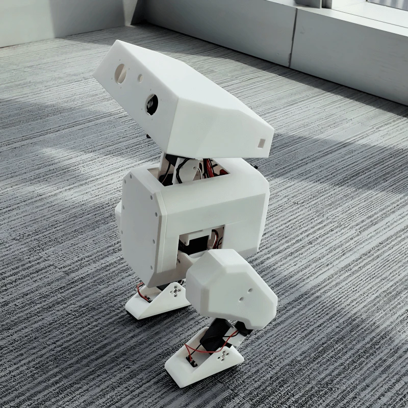
- The ES01 is an exciting open-source wheeled-legged robot powered by the ESP32 and SimpleFOC motor control. In this blog, we’ll walk you through the step-by-step process of assembling the hardware, integrating the motor control system, and deploying the software to bring your robot to life. Whether you’re a robotics enthusiast or a DIY maker, this guide will help you get started with your own ES01 robot!
ESP32 and Brushless Motors: Key Components of a Wheel-Legged Robot
- The ESP32, with its powerful dual-core processor, Wi-Fi/Bluetooth connectivity, and versatile peripheral interfaces, serves as an ideal control unit for robotics projects. Meanwhile, brushless motors (BLDC) offer high efficiency, low noise, and precise torque control—making them perfect for dynamic applications like wheel-legged robots, which require both mobility and stability.
- By leveraging the ESP32’s PWM outputs and sensor interfaces, developers can achieve smooth speed regulation and closed-loop control of brushless motors. This combination enables advanced locomotion in hybrid robots, allowing seamless transitions between wheeled and legged movement—ideal for navigating complex terrains. With wireless capabilities, the ESP32 further enhances functionality, enabling remote control, real-time telemetry, and smart autonomous behaviors.
- Whether for research, education, or innovative robotics designs, the ESP32 + BLDC motor duo provides a robust foundation for next-generation wheel-legged machines.
Code Overview
- Controls a brushless motor via PWM (using ESP32’s LEDC library).
- Supports ESC calibration (required for initial setup).
- Implements smooth acceleration/deceleration.
// Calibrate the ESC (must be done once before normal operation)
void calibrateESC() {
  Serial.println("Calibrating ESC...");
  Serial.println("1. Power ON the ESC NOW (wait for beeps).");
  Serial.println("2. After beeps, motor will arm at MIN_PULSE.");

  // Send max throttle pulse to enter calibration mode
  ledcWrite(0, MAX_PULSE);
  delay(3000);  // Wait for ESC detection

  // Send min throttle pulse to complete calibration
  ledcWrite(0, MIN_PULSE);
  delay(3000);  // Wait for ESC confirmation beeps
  Serial.println("Calibration complete!");
}

// Set motor speed (0% to 100%)
void setMotorSpeed(uint8_t speedPercent) {
  // Map percentage to pulse width (MIN_PULSE to MAX_PULSE)
  uint32_t pulse = map(speedPercent, 0, 100, MIN_PULSE, MAX_PULSE);
  ledcWrite(0, pulse);  // Send PWM signal to ESC
  Serial.print("Motor speed: ");
  Serial.print(speedPercent);
  Serial.println("%");
}

// Smooth acceleration/deceleration demo
void rampMotorSpeed(uint8_t targetSpeed, uint16_t durationMs) {
  uint8_t currentSpeed = 0;
  while (currentSpeed < targetSpeed) {
    setMotorSpeed(currentSpeed++);
    delay(durationMs / targetSpeed);  // Linear ramp
  }
}
Required Materials & Tools
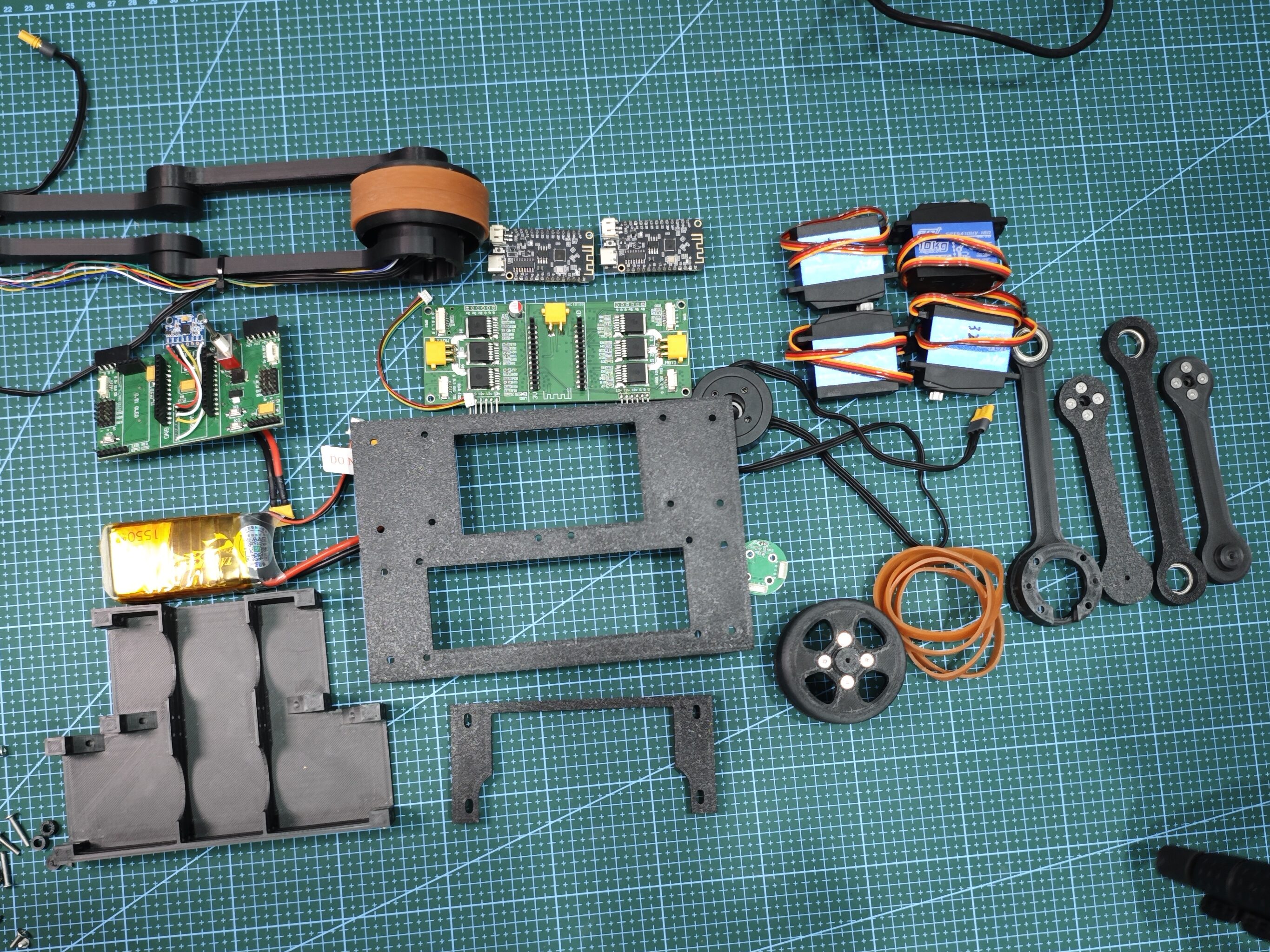
Hardware List
- ESP32 development board (preferably one with USB support)
- MPU6050 gyroscope module
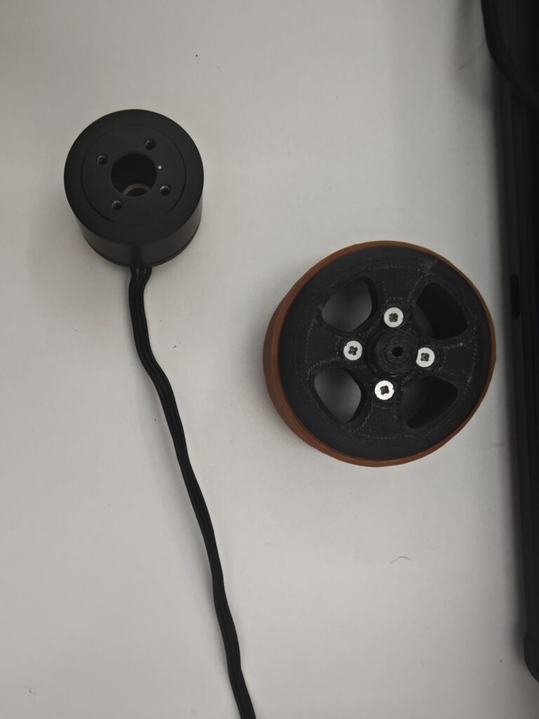
- 2× PM3510 brushless motors
- 2× SimpleFOC motor drivers
- 2× AS5600 magnetic encoders
- 3D-printed structural components (STL files available in the GitHub repo)
- Lithium battery (e.g., 18650)
- DC-DC buck converter or power management module
Hardware Assembly Guide
- Mount the servo motor onto the 3D-printed servo bracket.
- Install the brass standoffs for securing the gyroscope onto the mainboard support frame.
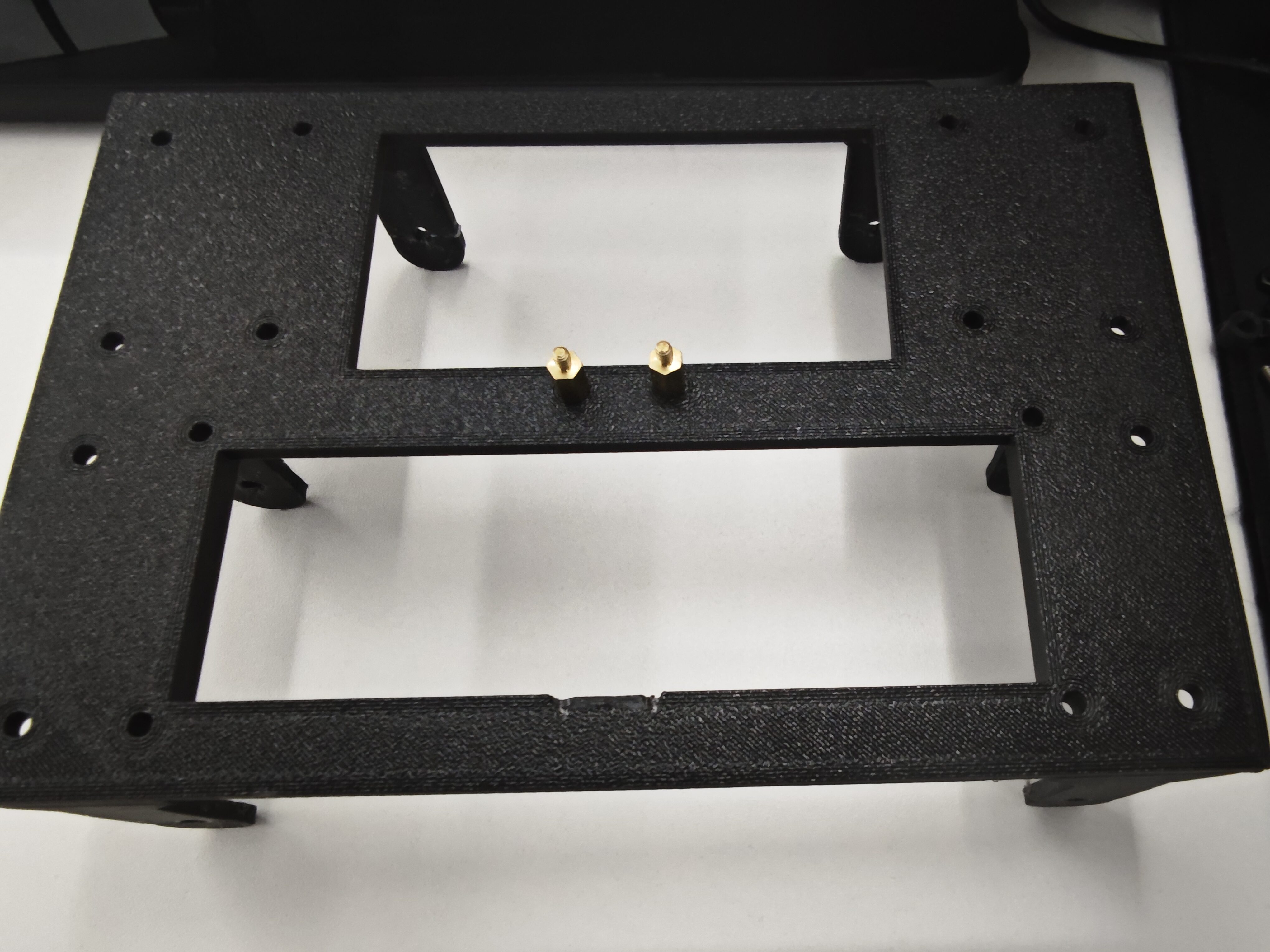
- Fix the mainboard onto the support frame and securely mount the MPU6050 gyroscope.
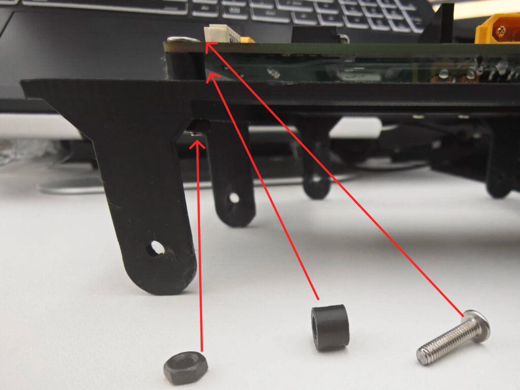
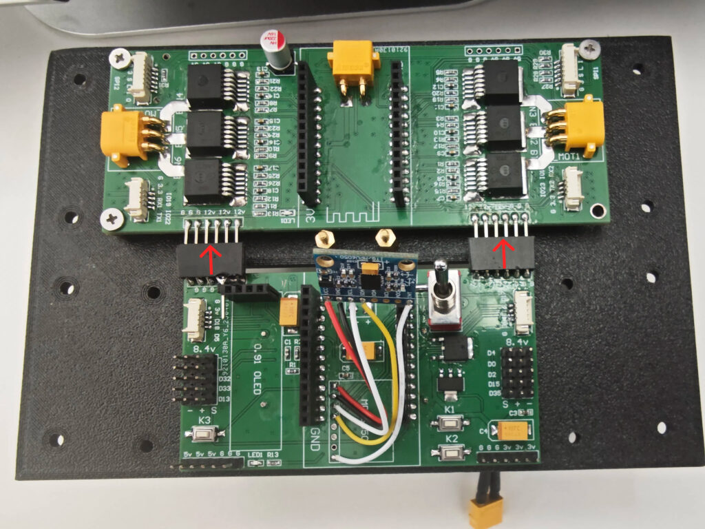
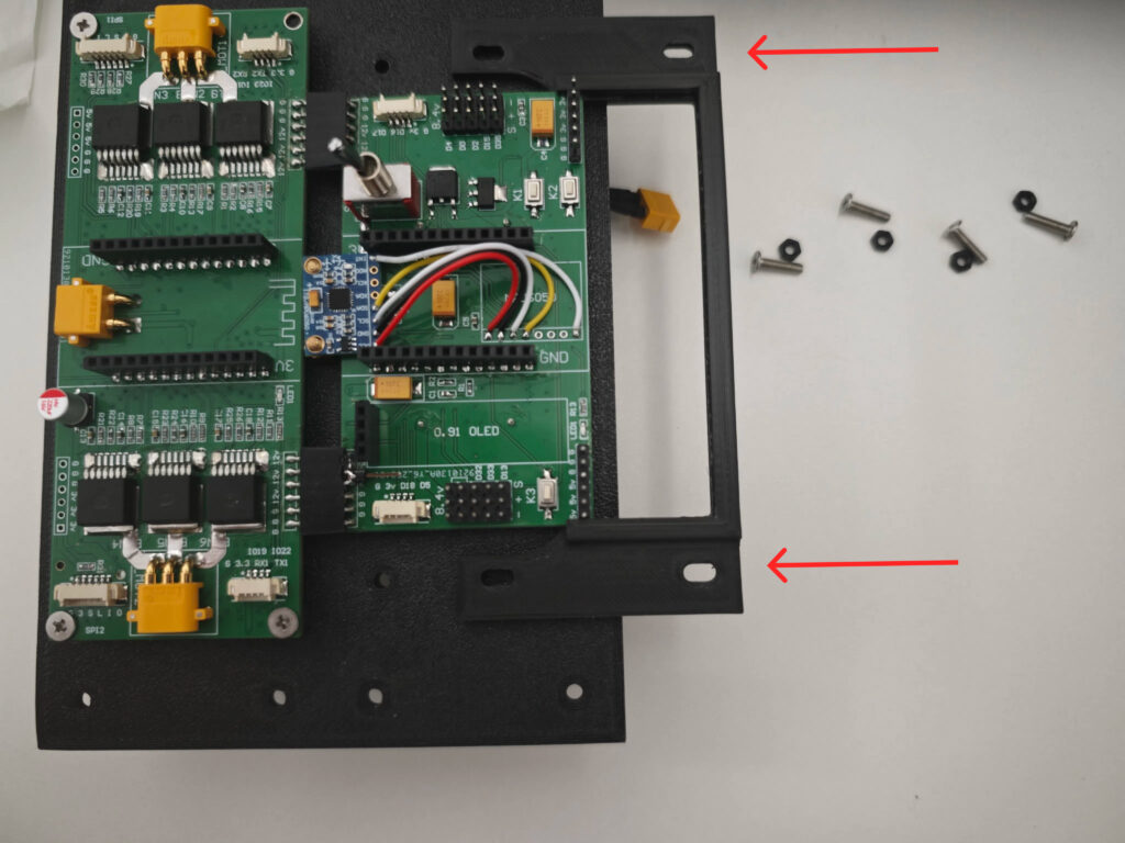
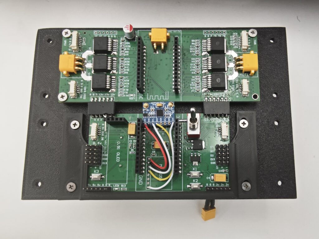
- Connect and fasten the mainboard support and servo bracket together. Manage the cables.
- Place the battery into the battery compartment.
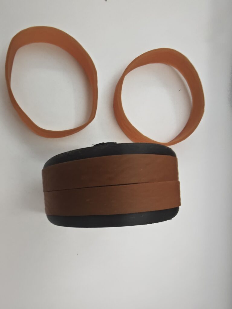
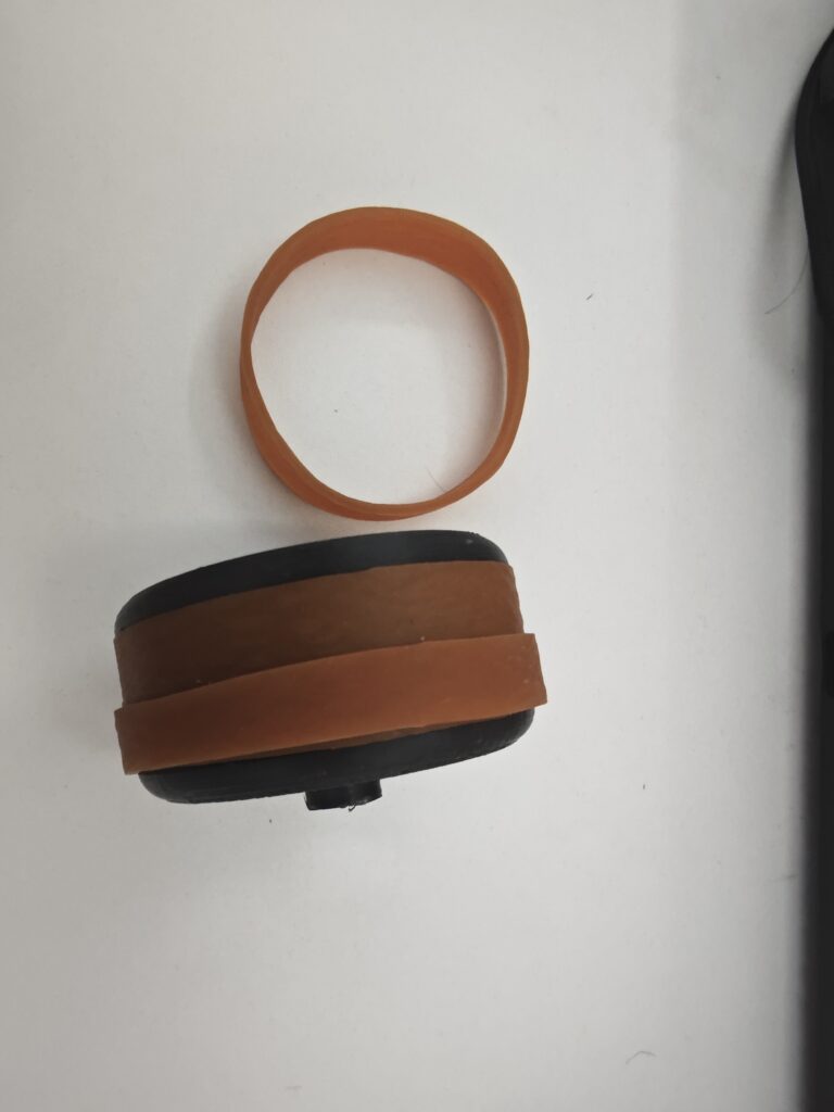
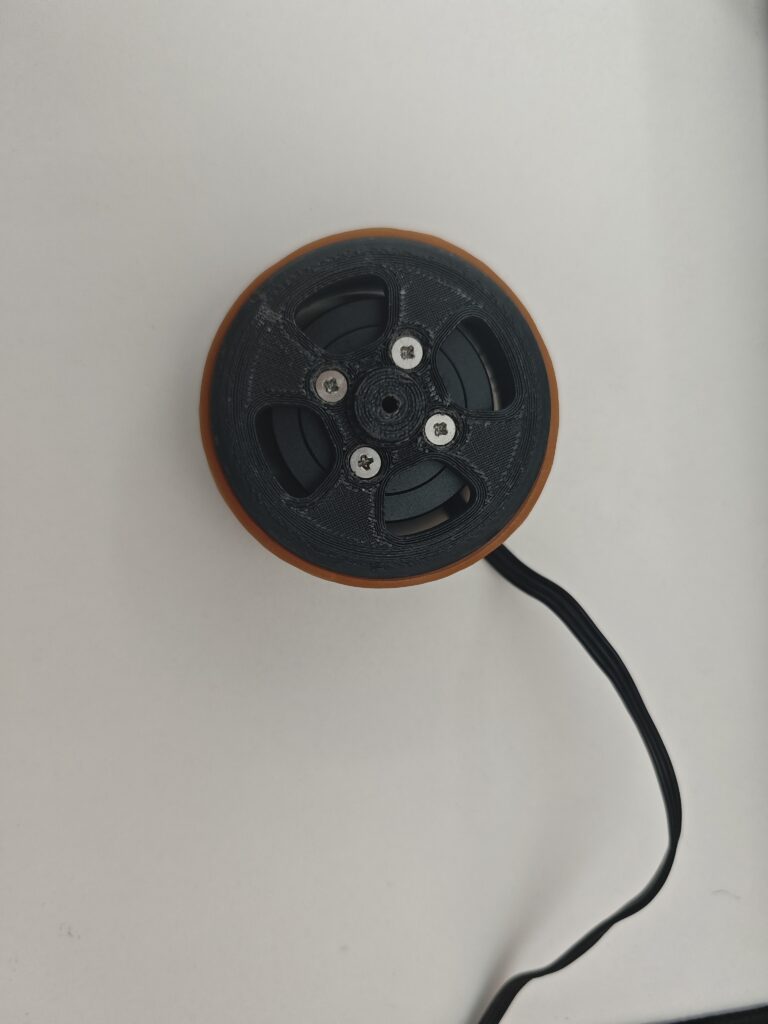
- Install the rubber tire onto the 3D-printed wheel.
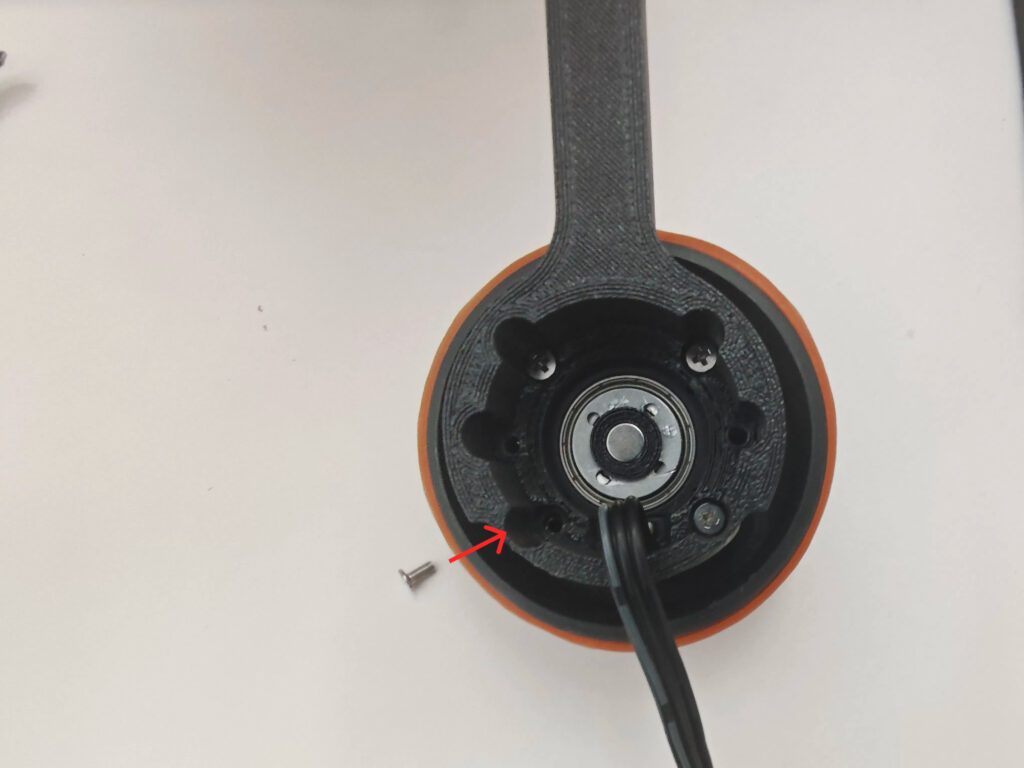
- Attach the brushless motors to the 3D-printed components.
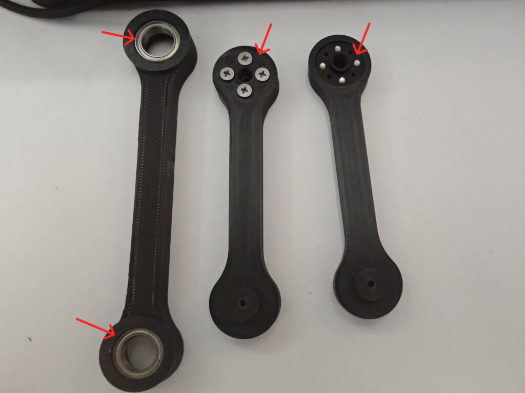
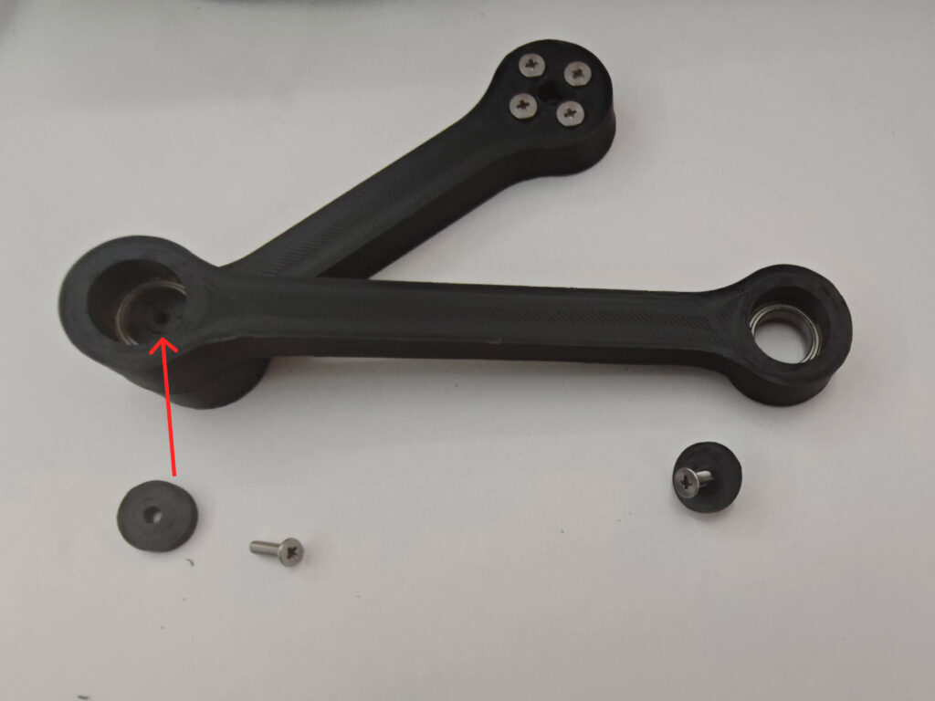
- Use glue to secure the bearings into the joint parts, then fasten the servo horn with screws.
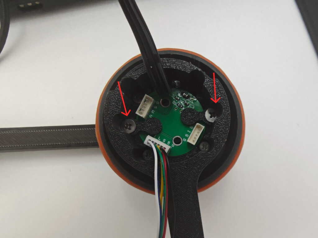
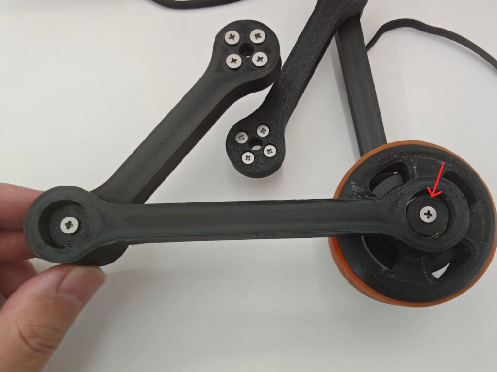
- Install the encoder onto the robot foot and connect the wires properly.
- Install the leg joint onto the wheeled leg.
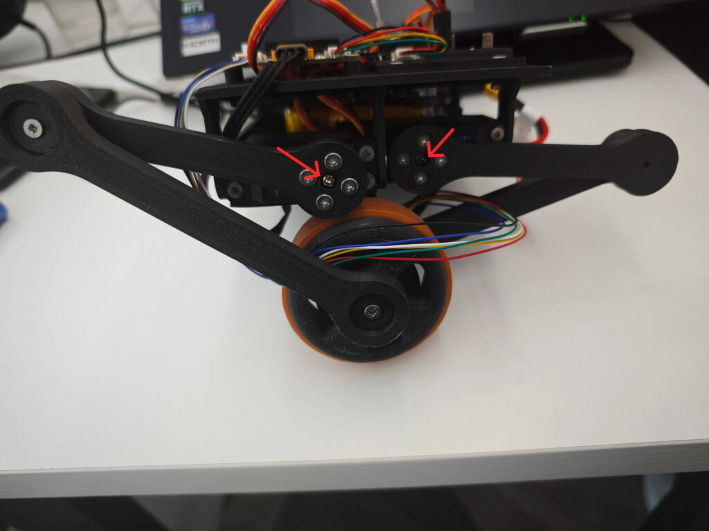
- Attach the complete leg assembly to the main body.
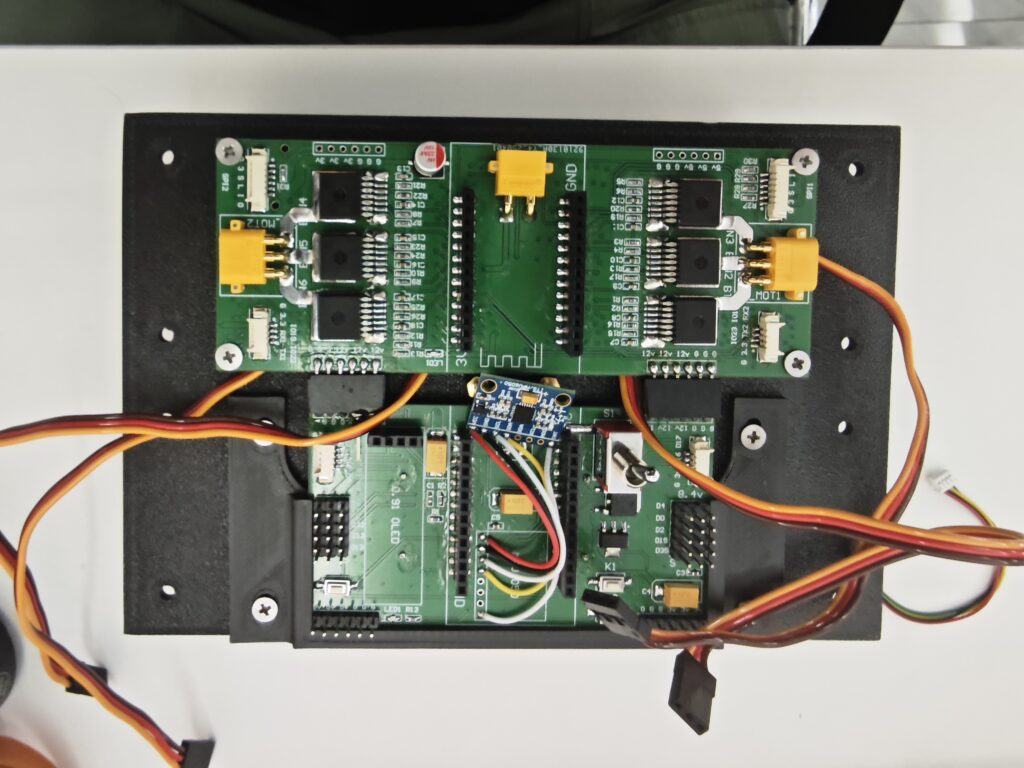
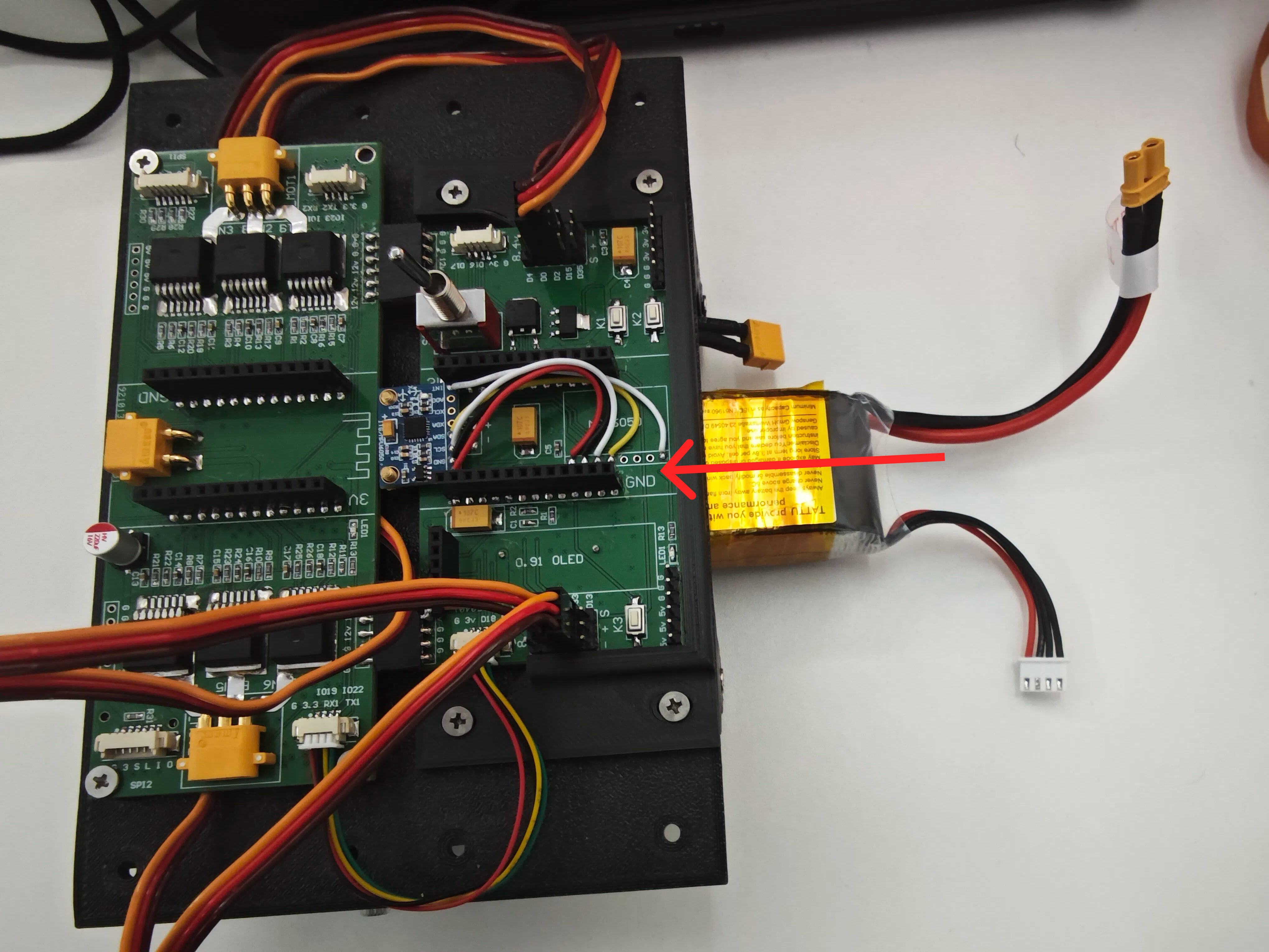
- Connect all remaining wires and finally attach the power cable.
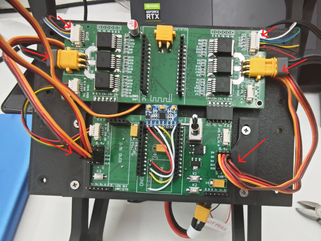
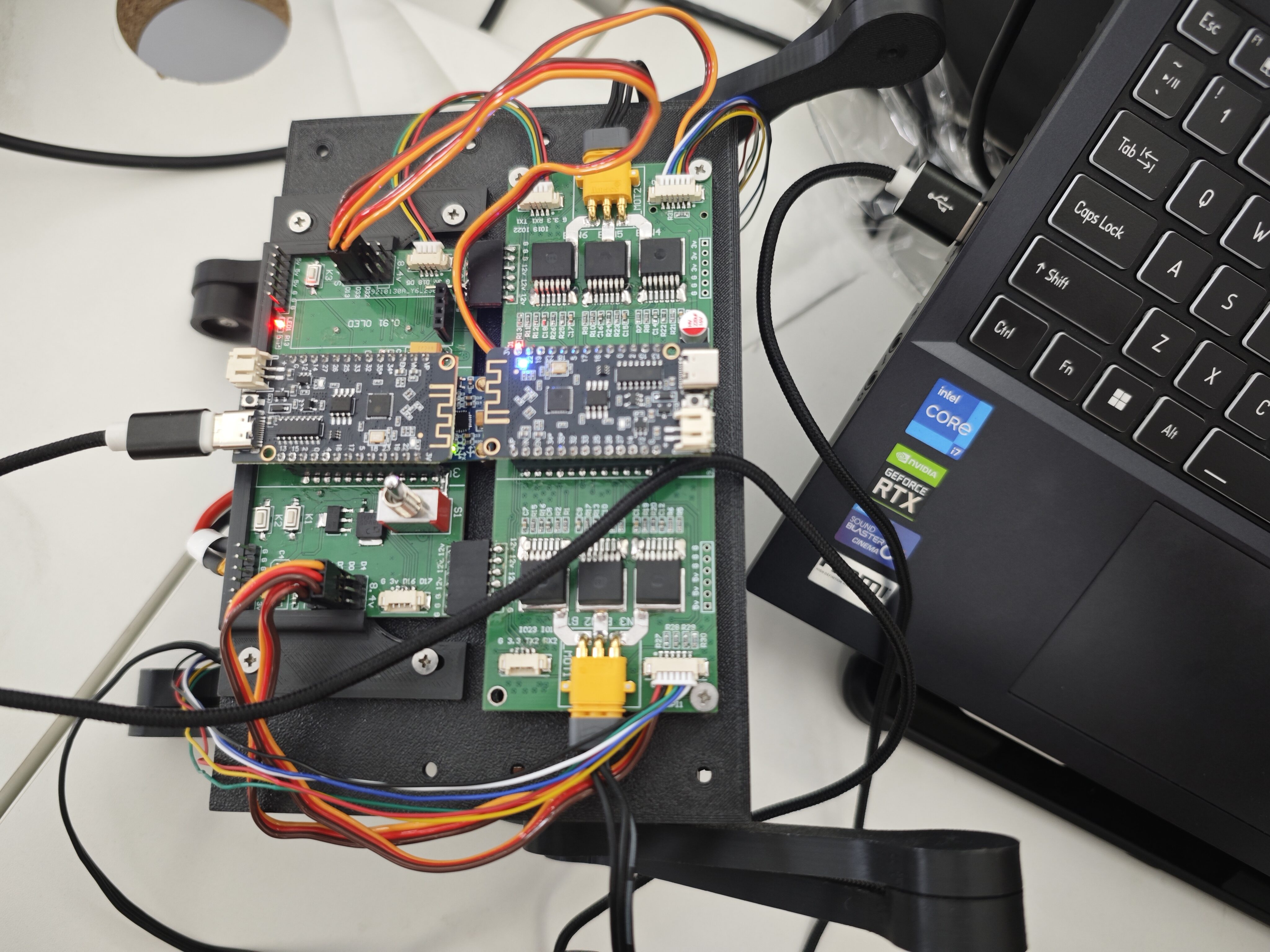
- Install the ESP32 microcontroller onto the mainboard.
Software Setup
- Install Arduino IDE
Download and install the Arduino IDE from the official Arduino website.
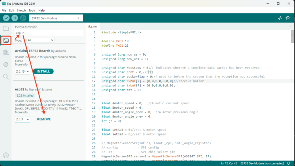
- Configure ESP32 Board Support
Then go to Tools > Board > Board Manager, search for “ESP32,” and install the board support package.
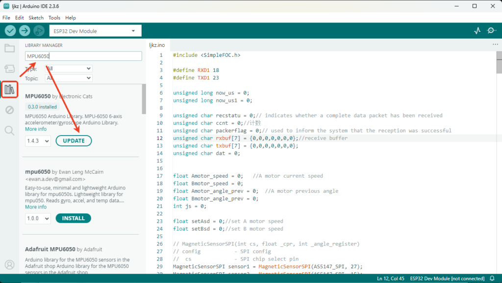
- Install Libraries
Open Manage Libraries, search for SimpleFOC, MPU6050(0.3.0),U8g2,and install the libraries.
- Upload Calibration Code:
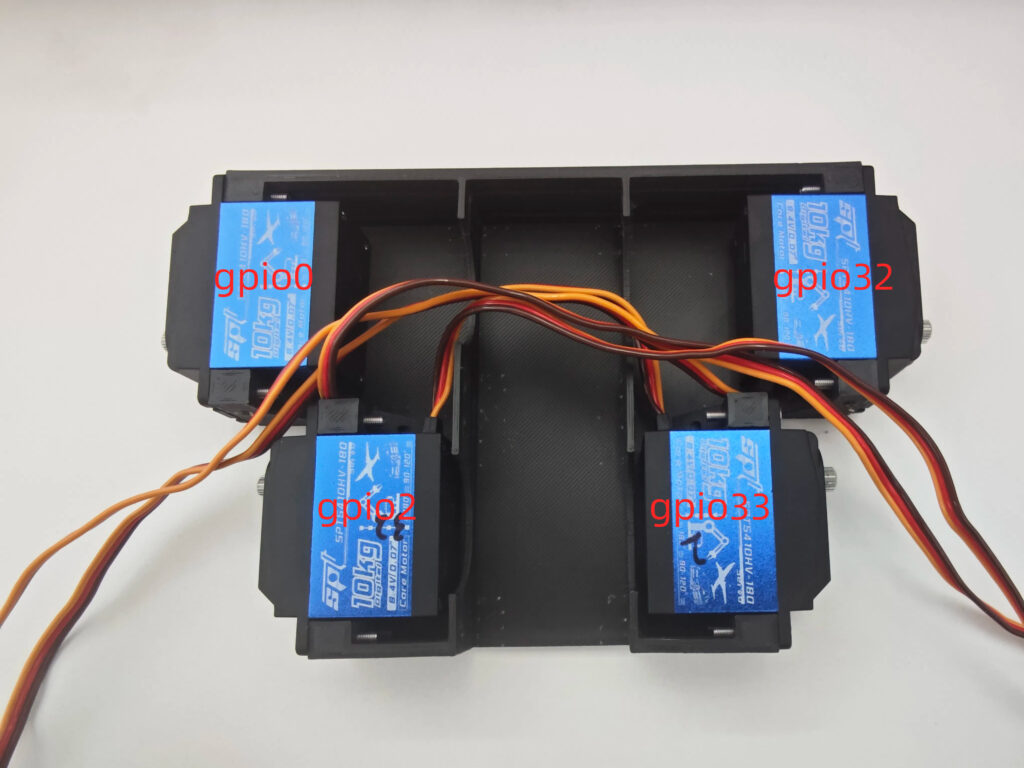
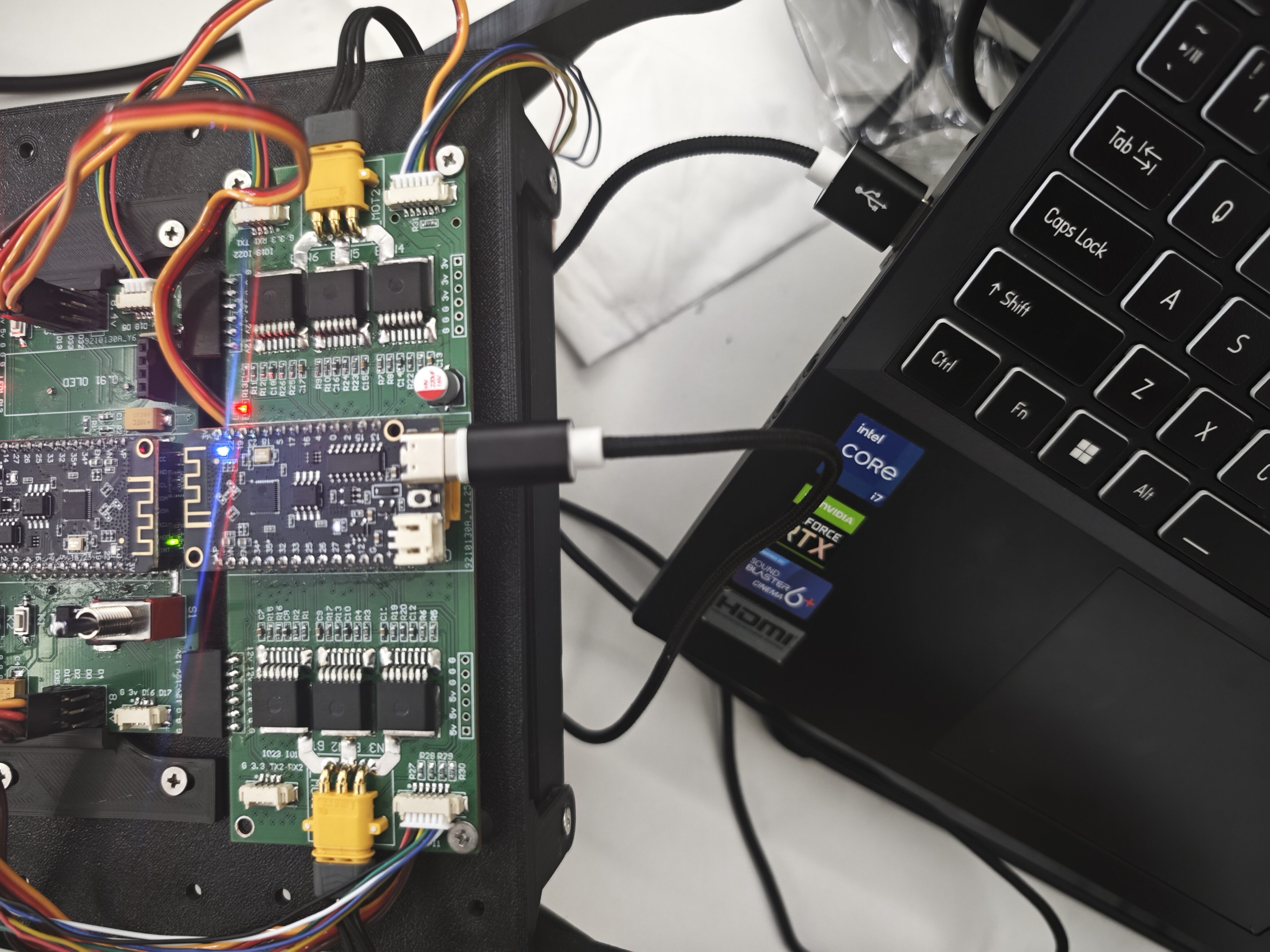
Open Foc_Drive.ino and connect the esp32 shown in the picture.
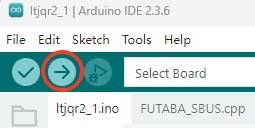
- Select ESP32 Dev Module and click Upload.
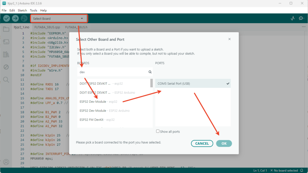
Open ES01_IMU.ino and connect the esp32 shown in the picture and upload.
Tips
- Encoder Magnet:
It’s recommended to use high-quality external magnets rather than relying on the motor’s built-in ones to ensure accurate encoder readings.
- MPU6050 Orientation:
If the MPU6050 is soldered onto the mainboard, you may need to adjust the pitch/roll angle calculation in code.
- Avoid Code Bloat:
Keep your code minimal during early testing to avoid slow refresh rates, which could cause jitter in the robot’s movement.
Resources
- GitHub Project: fuwei007/Navbot-ES01
- SimpleFOC Documentation: https://simplefoc.com/
- ESP32 Info: https://www.espressif.com/en/products/socs/esp32
This is the prototype of the wheeled-legged robot I developed. Although the PCB is a bit rough, its balancing algorithm is quite interesting. Feel free to try building one if you’re interested! Questions? Drop them in the comments.
👉 Subscribe for Robotics Deep Dives: YouTube/@frankfu007


Leave a Reply